ELECTRICAL
4181384 First Edition 4-67
4
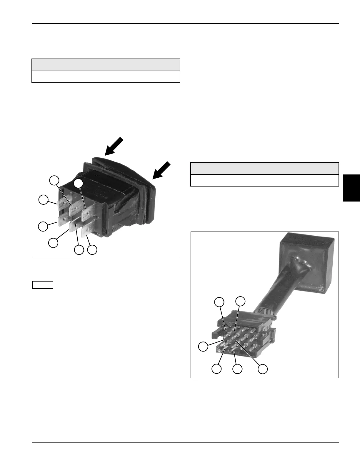
Park Brake Switch Test
See Figure 4-40.
1. Park the mower safely. (See “Park Mower Safely” on
page 1-7.)
2. Remove the switch from the instrument panel. (See
“Rocker Switches” on page 4-80.)
Figure 4-40
3. Place the switch in the off position.
NOTE
Use the alignment pin (4) as a reference point for correct
orientation.
4. Connect one test lead to terminal (5).
5. Connect the other test lead to terminal (6) and check
for continuity.
Is continuity indicated?
YES Proceed to step 6.
NO The switch is faulty; replace the switch.
6. Place the switch in the on position.
7. Move the test lead from terminal (5) to terminal (3)
and check for continuity.
Is continuity indicated?
YES Proceed to step 8.
NO The switch is faulty; replace the switch.
8. Connect one test lead to terminal (1).
9. Connect the other test lead to terminal (2) and check
for continuity.
Is continuity indicated?
YES Proceed to step 10.
NO The switch is faulty; replace the switch.
10. Place the switch in the off position.
11. Move the test lead from terminal (2) to terminal (7)
and check for continuity.
Is continuity indicated?
YES The switch is good.
NO The switch is faulty; replace the switch.
Diode Module Test
See Figure 4-41.
1. Park the mower safely. (See “Park Mower Safely” on
page 1-7.)
2. Remove the diode module. (See “Diode Module” on
page 4-78.)
Figure 4-41
3. Set the digital multimeter to the diode check setting.
4. Connect the test leads to terminals (1 and 2), and
record the reading.
Required Tools or Equipment
Digital Multimeter, Ohmmeter, or Continuity Tester
TN1156
OFF
ON
1
2
3
4
5
6
7
Required Tools or Equipment
Digital Multimeter
1
TN1153
2
3
4
5
6
 Loading...