CUTTING UNITS
4181384 First Edition 8-37
8
Figure 8-31
Figure 8-32
5. Remove four (two each side) screws (2), and remove
the bedknife shoe assembly.
Installation Note
• Install the bedknife shoe assembly by reversing the
order of removal.
• Apply anti-seize compound to the threads of the
bedknife shoe mounting screws before installing.
• Adjust the bedknife-to-reel contact. (Refer to “Safety,
Operation, and Maintenance Manual”.)
Bedknife
Removal and Installation
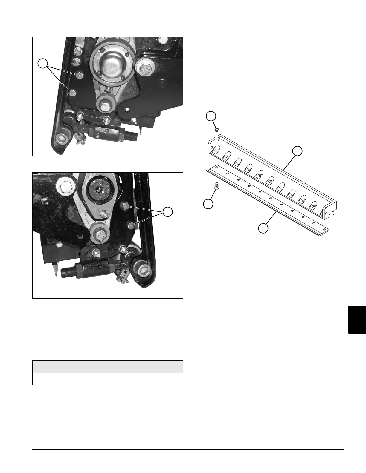
See Figure 8-33.
1. Park the mower safely. (See “Park Mower Safely” on
page 1-7.)
2. Remove the bedknife shoe assembly. (See “Bedknife
Shoe” on page 8-36.)
Figure 8-33
3. Remove 11 lock nuts (1) and screws (4), and remove
the bedknife (3) from the bedknife shoe (2).
Installation Notes
• Install the bedknife by reversing the order of removal.
• Adjust the bedknife-to-reel contact. (Refer to “Safety,
Operation, and Maintenance Manual”.)
Required Materials
Anti-Seize Compound
TN1260
2
TN1261
2
TN1268
2
4
1
3
 Loading...