ELECTRICAL
4181384 First Edition 4-83
4
NOTES
• Record the orientation of the joystick before removing
to ensure correct installation.
• When removed, the joystick may come out as two
separate pieces. If the joystick is to be tested after
removal, connect the two pieces together using the
mounting hardware.
6. Remove four lock nuts (8), flat washers (9), and
screws (2), and remove joystick (7) from instrument
panel (3).
Installation Note
Install the joystick by reversing the order of removal.
Control Module
Removal and Installation
See Figure 4-77.
1. Park the mower safely. (See “Park Mower Safely” on
page 1-7.)
2. Disconnect the battery negative (–) cables at the
battery.
3. Remove instrument panel. (See “Instrument Panel”
on page 4-76.)
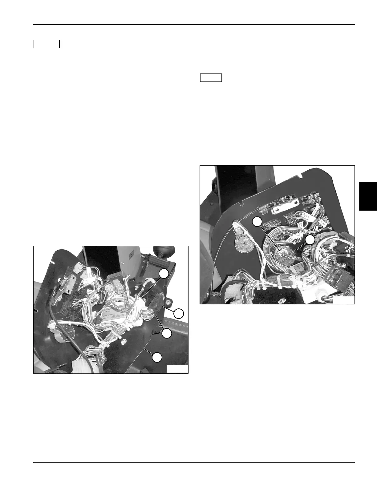
Figure 4-77
4. Disconnect the control module wiring connector (2)
from the harness (3).
5. Remove the control module (1) from the instrument
panel (4).
Installation Note
Install the control module by reversing the order of
removal.
Multi-Function Gauge
Removal and Installation
See Figures 4-78 and 4-79.
NOTE
Remove the multi-function gauge only if replacement is
required. Removal of the retainer bracket will result in
damage to the bracket.
1. Park the mower safely. (See “Park Mower Safely” on
page 1-7.)
2. Disconnect the battery negative (–) cables at the
battery.
3. Remove instrument panel. (See “Instrument Panel”
on page 4-76.)
Figure 4-78
4. Disconnect the wiring connector (1) from the
multi-function gauge (2).
TN1148
2
3
4
1
1
TN1099
2
 Loading...