ELECTRICAL
4181384 First Edition 4-85
4
Solenoid Coils
See Figures 4-81 and 4-82.
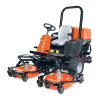
Figure 4-81: Mow and Brake Solenoid Coils
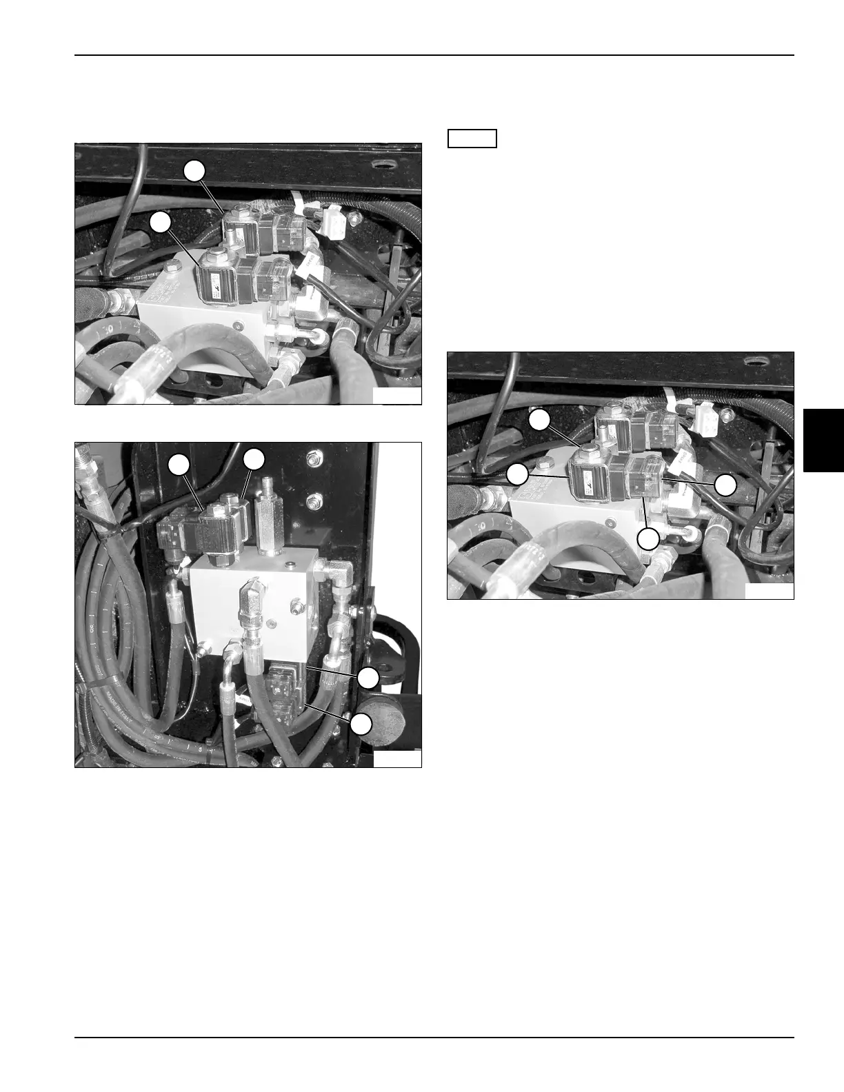
Figure 4-82
This procedure applies to the following solenoid coils:
• Brake Solenoid Coil (1)
• Mow Solenoid Coil (2)
• Weight Transfer Solenoid Coils (3 and 4)
• Lower Solenoid Coil (5)
• Lift Solenoid Coil (6)
The brake and mow solenoid coils are located under the
seat platform.
The lift, lower, and weight transfer solenoid coils are
located under the foot platform.
Removal and Installation
See Figure 4-83.
NOTE
The mow solenoid is shown; all solenoids are removed
and installed the same way.
1. Park the mower safely. (See “Park Mower Safely” on
page 1-7.)
2. Raise and support the seat platform (mow and brake
solenoids) or remove the left front mower deck (raise,
lower, and weight transfer solenoids). (See “Rotary
Cutting Unit” on page 8-25.)
3. Disconnect the battery negative (–) cables at the
battery.
Figure 4-83
4. Remove screw (8), and disconnect connector block
(9) from the solenoid coil (10).
5. Remove nut (7), and remove the solenoid coil (10)
from the valve.
Installation Notes
• Install the solenoid coils by reversing the order of
removal.
• Tighten nut (7) to 36 lb-in. (4.1 N·m).
1
TN1161
2
TN1162
3
4
5
6
TN1161
8
9
7
10
 Loading...