8-36 4181384 First Edition
CUTTING UNITS
8
Cutting Unit
Removal and Installation
See Figures 8-27 through 8-29.
1. Park the mower safely. (See “Park Mower Safely” on
page 1-7.)
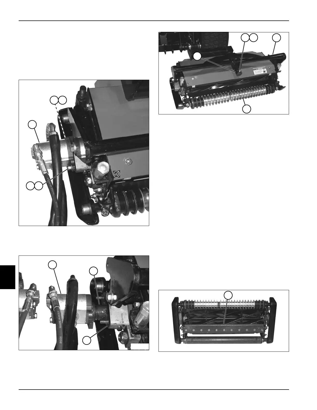
Figure 8-27
2. Remove two nuts (2) and lock washers (3) from drive
motor (1).
Figure 8-28
3. Remove the drive motor (4), coupler (5), and gasket
(6) from the cutting unit, and move the motor aside.
Figure 8-29
4. Remove the socket-head screw (8), lock washer (9),
and collar (7) from the yoke shaft.
5. Remove the cutting unit (11) from the yoke assembly
(10).
Installation Notes
• Install the cutting unit by reversing the order of
removal.
• Inspect O-rings on fittings before installation.
Replace O-rings if damaged or missing.
• Use a new gasket for installation.
• Apply grease to the yoke shaft lubrication fitting and
drive motor coupling. (Refer to “Safety, Operation,
and Maintenance Manual” for grease specifications.)
Bedknife Shoe
Removal and Installation
See Figures 8-30 through 8-32.
1. Park the mower safely. (See “Park Mower Safely” on
page 1-7.)
2. Remove the cutting unit. (See “Cutting Unit” on
page 8-36.)
Figure 8-30
3. Place the cutting unit on a solid work surface, with it
resting on its back.
4. Support the bedknife shoe assembly (1).
TN1126
2 3
1
2 3
TN1181
4
5
6
TN1163
7
10
8 9
11
TN1257
1
 Loading...