4-76 4181384 First Edition
ELECTRICAL
4
Instrument Panel
Removal and Installation
See Figures 4-56 through 4-58.
NOTE
If servicing individual components, it is not necessary to
completely remove the instrument panel. In these cases
the instrument panel can be moved aside for access to
components.
1. Park the mower safely. (See “Park Mower Safely” on
page 1-7.)
NOTE
Label all wires before disconnecting to ensure correct
installation.
2. Disconnect the battery negative (–) cables at the
battery.
3. If removing the instrument panel, disconnect the
positive (+) cables from the battery.
4. Raise and support the seat platform.
Figure 4-56
NOTES
• Seat removed for photo clarity.
• If moving the instrument panel aside, use caution to
prevent stretching or kinking of the cables.
5. Remove six screws (1) and move the panel (2) aside,
or service components as needed.
NOTE
If removing the instrument panel, proceed to steps 6
through 9.
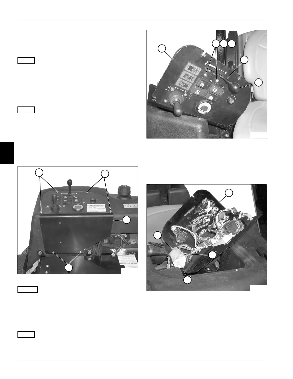
Figure 4-57
6. Remove (unscrew) the knob (8) from the throttle
control lever assembly (7).
7. Remove two lock nuts (4), flat washers (5), and
screws (6), and remove throttle control lever
assembly (7) from instrument panel (3).
Figure 4-58
8. Disconnect three wiring connectors (10, 11 and 12)
from the harness.
9. Remove the instrument panel (9).
Installation Note
Install the instrument panel by reversing the order of
removal.
TN1057
1
1
2
1
3
TN1150
8
4
5
6
7
9
TN1151
12
10
11
 Loading...