CUTTING UNITS
4181384 First Edition 8-31
8
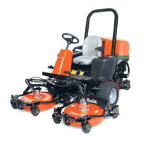
Figure 8-16
8. Inspect yoke bushings (8) for wear and damage and
replace as necessary.
Installation Notes
• Install the deck caster wheel by reversing the order of
removal.
• Apply grease to grease fitting (9). (Refer to “Safety,
Operation, and Maintenance Manual” for grease
specifications.)
Mower Deck
Removal and Installation
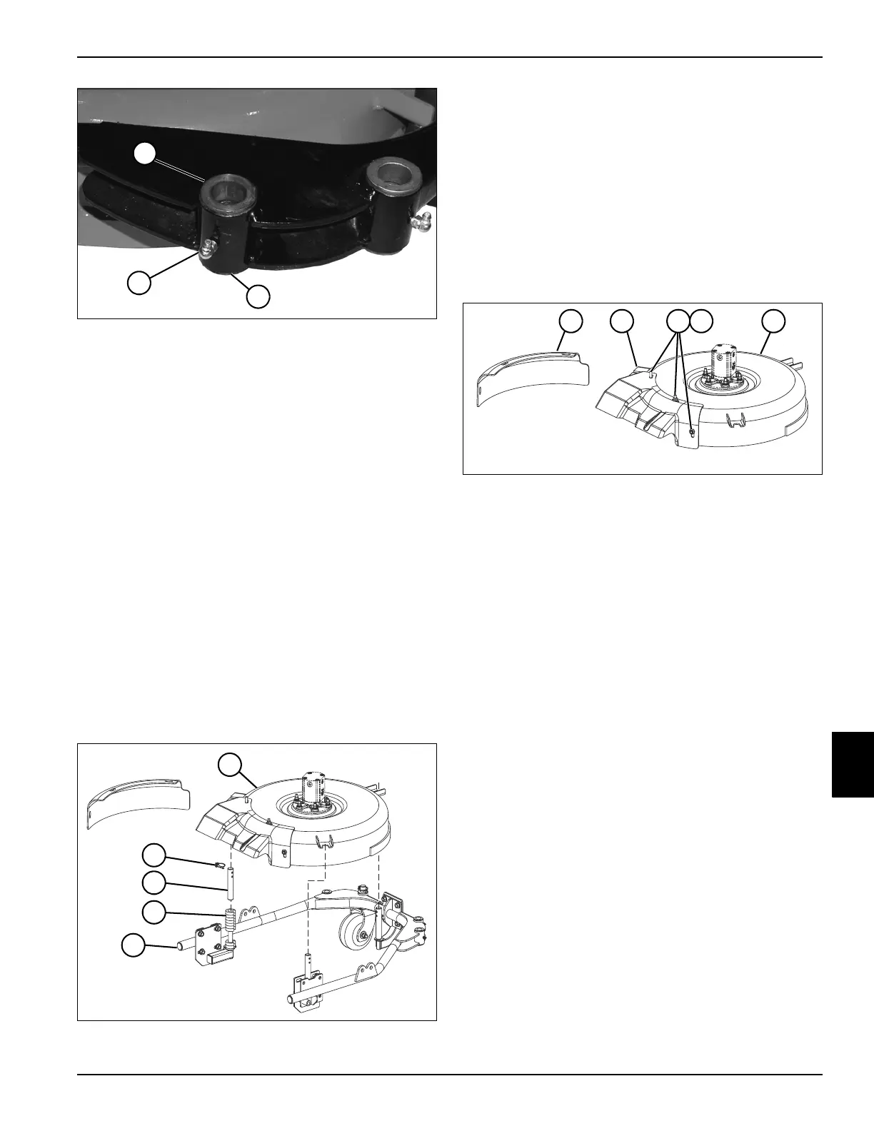
See Figure 8-17.
1. Park the mower safely. (See “Park Mower Safely” on
page 1-7.)
2. Remove cutting unit. (See “Rotary Cutting Unit” on
page 8-25.)
3. Remove deck yoke. (See “Front Deck Yoke” on
page 8-29.) (See “Rear Deck Yoke” on page 8-29.)
Figure 8-17
4. Remove three snap ring lock pins (2) and spacers (4)
from cutting height spindles (3) of cutting unit frame
(5).
5. Lift mower deck (1) up and away from cutting unit
frame (5).
Installation Note
Install the mower deck by reversing the order of removal.
Disassembly and Assembly
See Figure 8-18.
Figure 8-18
1. Remove three nuts (3) and washers (not shown) from
screws (4)
2. Remove mulch cover (1) or deflector (2) from mower
deck (5).
Assembly Note
Assemble the mower deck by reversing the order of
disassembly.
Deck Roller
Removal and Installation
See Figures 8-19 and 8-20.
1. Park the mower safely. (See “Park Mower Safely” on
page 1-7.)
2. Remove deck yoke. (See “Front Deck Yoke” on
page 8-29 or “Rear Deck Yoke” on page 8-29.)
3. Remove mower deck. (See “Mower Deck” on
page 8-31.)
TN1326
8
8
9
TN1195
3
2
4
1
5
TN1330
521 3 4
 Loading...