ELECTRICAL
4181384 First Edition 4-65
4
7. With the test leads connected as described in step 6,
move and hold the joystick in the raise position.
Is continuity indicated?
YES The switch/joystick assembly is good.
NO The switch is faulty; replace the joystick
assembly.
Traction Pedal Neutral Switch Test
See Figure 4-36.
1. Park the mower safely. (See “Park Mower Safely” on
page 1-7.)
Figure 4-36
2. Remove traction pedal neutral switch from mower.
(See “Traction Pedal Neutral Switch” on page 4-84.)
3. Connect test leads to the switch terminals (1 and 2).
4. Actuate traction pedal neutral switch.
5. Check for continuity.
Is continuity indicated?
YES The switch is good.
NO The switch is faulty; replace the switch.
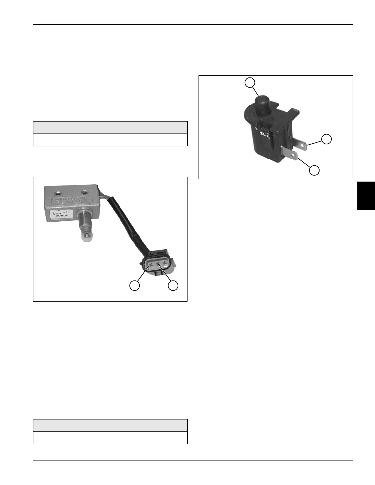
Seat Switch Test
See Figure 4-48.
1. Park the mower safely. (See “Park Mower Safely” on
page 1-7.)
2. Remove the seat switch from the seat cushion. (See
“Seat and Mounting Plate” on page 9-16.)
Figure 4-37
3. Connect test leads to the switch terminals (2 and 3).
4. Check for continuity.
Is continuity indicated?
YES The switch is faulty; replace the switch.
NO Proceed to step 5.
5. Press and hold the plunger (1) down and check for
continuity.
Is continuity indicated?
YES The switch is good.
NO The switch is faulty; replace the switch.
Required Tools or Equipment
Digital Multimeter, Ohmmeter, or Continuity Tester
Required Tools or Equipment
Digital Multimeter, Ohmmeter, or Continuity Tester
1
TN1214
2
2
TN1029
3
1
 Loading...