4-78 4181384 First Edition
ELECTRICAL
4
Diode Module
Removal and Installation
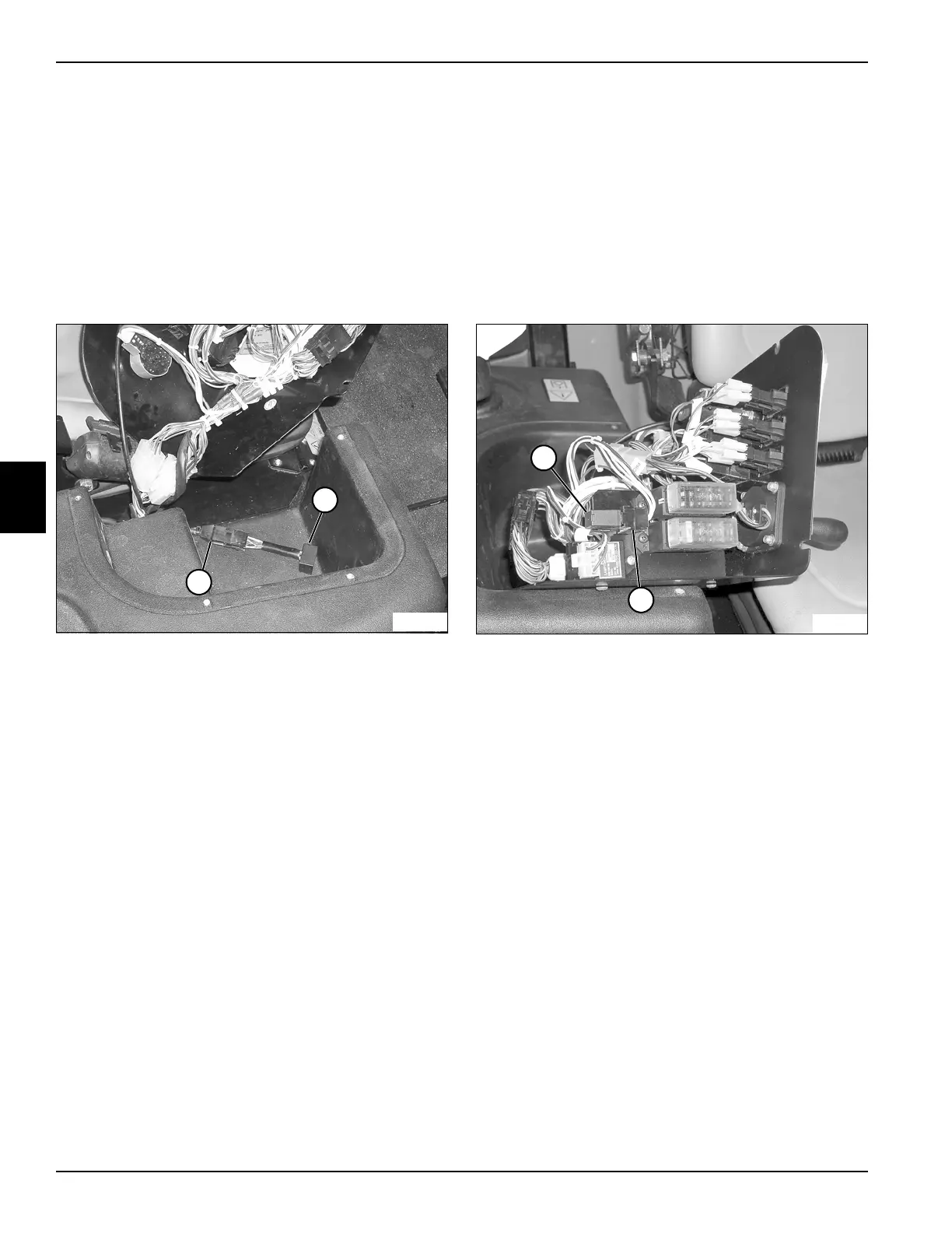
See Figure 4-63.
1. Park the mower safely. (See “Park Mower Safely” on
page 1-7.)
2. Disconnect the battery negative (–) cables at the
battery.
3. Remove instrument panel. (See “Instrument Panel”
on page 4-76.)
Figure 4-63
4. Disconnect the diode module (1) from the harness
(2).
Installation Note
Install the diode module by reversing the order of
removal.
Start Relay
Removal and Installation
See Figure 4-64.
1. Park the mower safely. (See “Park Mower Safely” on
page 1-7.)
2. Disconnect the battery negative (–) cables at the
battery.
3. Remove instrument panel. (See “Instrument Panel”
on page 4-76.)
Figure 4-64
4. Pull the relay (1) straight up and out of the relay base
(2).
Installation Note
Install the start relay by reversing the order of removal.
1
TN1152
2
1
TN1127
2
 Loading...