4-82 4181384 First Edition
ELECTRICAL
4
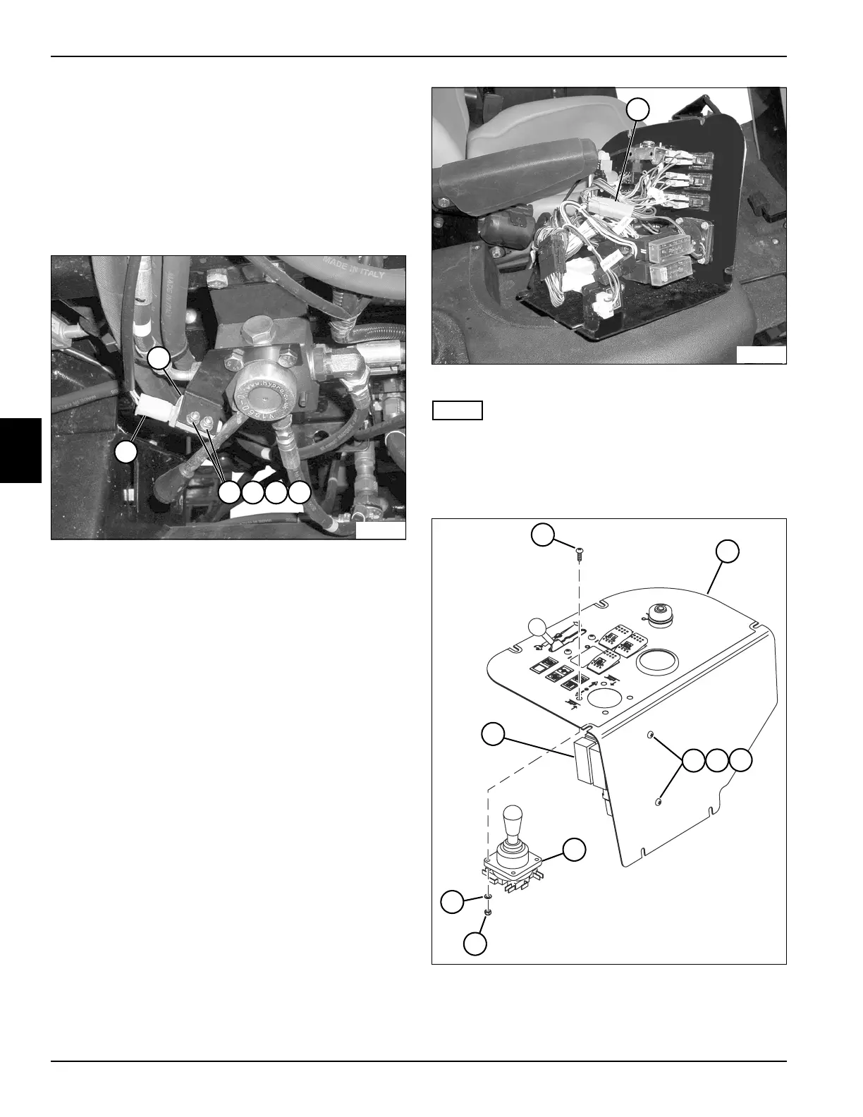
Brake Safety Switch
Removal and Installation
See Figure 4-74.
1. Park the mower safely. (See “Park Mower Safely” on
page 1-7.)
2. Disconnect the battery negative (–) cables at the
battery.
Figure 4-74
3. Disconnect the wiring connector (1) from the brake
safety switch (6).
4. Remove two lock nuts (2), flat washers (3), and
screws (4), and remove clamp plate (5) and brake
safety switch (6).
Installation Note
Install the brake safety switch by reversing the order of
removal.
Joystick
Removal and Installation
See Figures 4-75 and 4-76.
1. Park the mower safely. (See “Park Mower Safely” on
page 1-7.)
2. Disconnect the battery negative (–) cables at the
battery.
3. Remove instrument panel. (See “Instrument Panel”
on page 4-76.)
Figure 4-75
NOTE
Label all wiring connectors before removing to ensure
correct installation.
4. Disconnect the joystick wiring connector (1) from the
wiring harness.
Figure 4-76
5. Remove two lock nuts (4), flat washers (5), and
screws (6), and move the fuse block bracket
assembly (10) aside.
6
TN1158
1
2
3
4
5
1
TN1093
TN1094
9
8
7
10
4
5
6
2
3
 Loading...