Rev. 2.0
Maintenance Guide
1-89
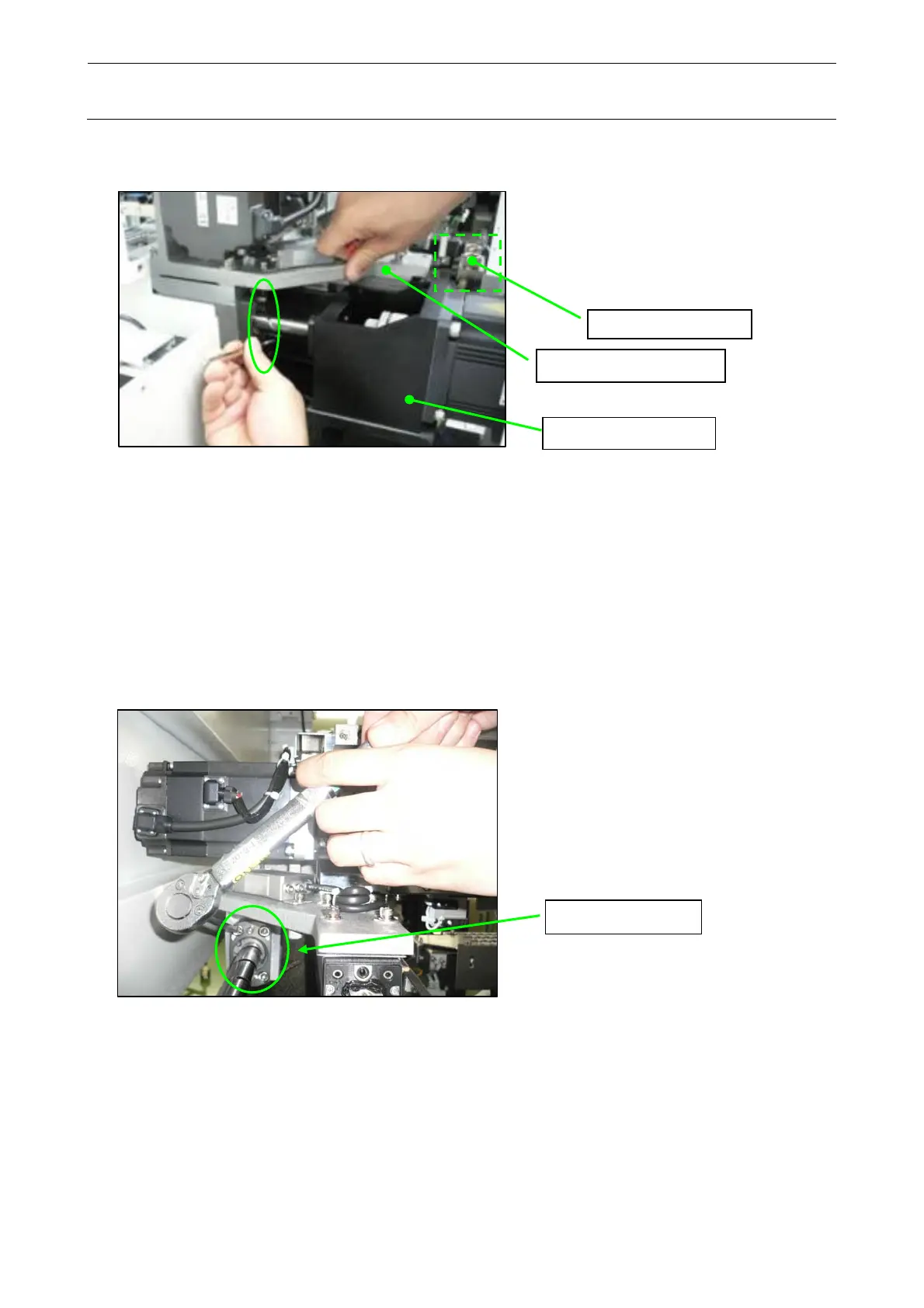
(3) After checking, move the X_AXIS_FRAME_ASM to the front until it is in contact with the
Y_STOPPER, and then retighten the screws (SM6062002TN, 2 pcs.) outside the machine.
X_AXIS_FRAME_ASM
Y_MOTOR_FRAME
Y
STOPPER
ASM
(4) Reciprocate the HEAD_UNIT several times again until the X_AXIS_FRAME_ASM is in
contact with both the Y_STOPPER on the front and the Y_STOPPER on the rear to check
that the movement is smooth.
After tightened firmly, measure the sliding load and check that the measured value is 120[N]
or less.
If the measured value does not satisfy the standard level, make the adjustment again from
step 1-9-4 (3).
(For details about how to measure the sliding load of the Y-axis, see step 1-9-4 (6).)
(5) Move the X_AXIS_FRAME_ASM to the front until it is in contact with the Y_STOPPER.
Tighten all of four fixing screws (SM6062002TN) of the Y ball screw nut.
Y_ball screw_nut
 Loading...


