Rev. 2.0
Maintenance Guide
2-16
2-5. Replacing the Head Up Cylinder
1) Turn the finger valve to stop the air supply and disconnect the air tubes.
2) Remove the head up springs from both ends, and then remove the nut from the top end of the
air cylinder to detach the release bar. (Pay special attention so that the wave washer is not
lost.)
3) Loosen the setscrews of the auto switch.
4) Remove the M3×30 cap bolts securing the air cylinder and detach the air cylinder.
5) When mounting the air cylinder, adjust the end face so that it is in parallel to the cylinder
mount and secure them.
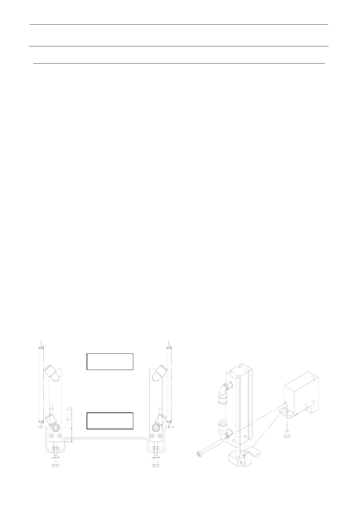
6) Mount the auto switch. At this time, mount the auto switch at a position 16.5mm from the
lower end of the cylinder.
7) If the speed controller has also been replaced, it is necessary to carry out the adjustment
before mounting the release bar.
<Speed controller adjustment procedure>
c Call up the MS parameters from the top menu and select [Simple Control] → [MSP] tab in the
function bar. In this status, press the emergency stop button.
d Select [nozzle up cylinder] and turn ON or OFF the cylinder to adjust the displayed time
(msec.) to the specification value. Adjust the time by turning the knob of the speed controller.
Specification value: Air cylinder down time 120±5 msec.
(The difference between the left and right is 5 msec. or less.)
After the adjustment has been completed, secure the knob firmly.
8) Insert the release bar into the rod of the cylinder, put the wave washer, and turn the release
bar until the cylinder nut is stopped.
Secure the cylinder at a position where the lower nut is aligned with the end face of the rod.
For the air cylinder on the IC head, remove two screws shown in the Figure on the right and
replace the cylinder.
(At this time, it is not necessary to adjust the speed controller and MS parameter.)
∗ Manually operate the solenoid valve to check that the release bar moves up or down
smoothly.
Air cylinder
Release bar
(Auto switch position)
KE-3020V (IC head side)
 Loading...


