Rev. 2.0
Maintenance Guide
1-88
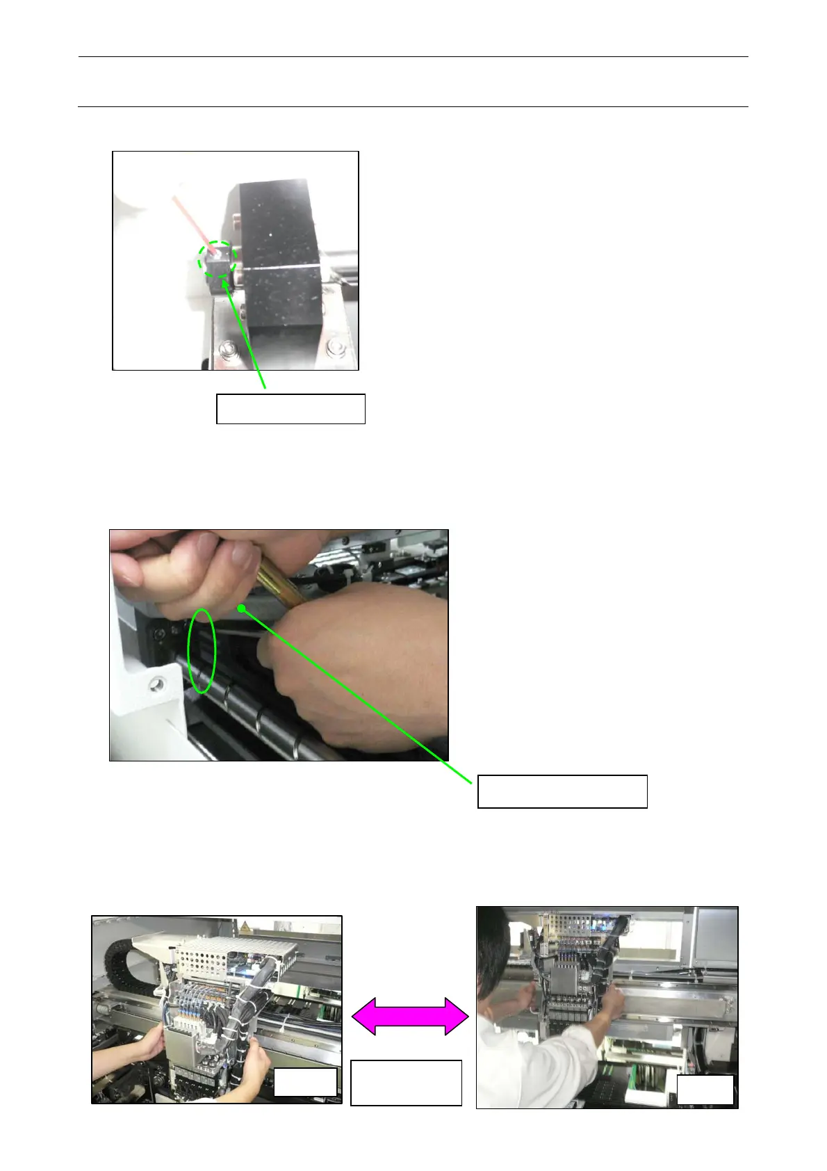
3) Tighten the set screw of the lock nut.
Set screw of lock nut
1-9-4. Adjusting the Y Ball Screw
(1) Move the X_AXIS_FRAME_ASM to a front limit where the wrench can be put, and then
retighten the screws (2 pcs.) (SM6062002TN) inside the machine.
X_AXIS_FRAME_ASM
(2) Reciprocate the HEAD_UNIT several times until the X_AXIS_FRAME_ASM is in contact
with both the Y_STOPPER on the front and the Y_STOPPER on the rear to check that the
movement is smooth.
If the movement is not smooth, make the adjustment again from step 1-9-4 (1).
Front
Rear
Repeat
several times.
 Loading...


