Rev. 2.0
Maintenance Guide
1-21
1-3-2. Replacing the Y-Axis Limit Sensor and the Y-Axis Home Proximity Sensor
∗ If only the sensor is replaced, it is not necessary to adjust the position.
∗ If the sensor is replaced together with the bracket, it is necessary to adjust the position.
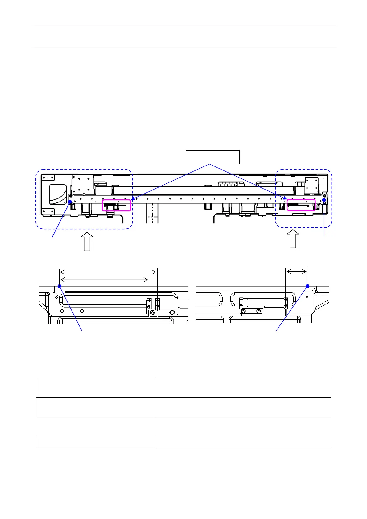
1) Loosen the screws fixing the Y-limit sensor bracket and make the adjustment so that the
distances from the split pin mounting center position of the base frame are those shown in
the Figure below. After the adjustment has been completed, tighten the screws firmly. (See
Figure 1-3-2-1 (M and L board specifications) and Figure 1-3-2-2 (XL board specifications).)
<M and L board specifications>
Split pin
Split pin
Viewed from A
Viewed from B
Y-limit sensor
67.5
Split pin hole part
Split pin hole part
162
177
Figure 1-3-2-1 M and L Board Specifications
Front side (Y negative limit sensor) Distance from the split pin mounting center position on the front of the
base frame to the center of the sensor: 162 mm
Front side 2 (Y near sensor) Distance from the split pin mounting center position on the front of the
base frame to the center of the sensor: 177 mm
Rear side 2 (Y ++ limit sensor) Distance from the split pin mounting center position on the rear of the
base frame to the center of the sensor: 67.5 mm
Clearance between the limit sensor and the dog
1.8 to 2.5 mm (target: 2.0 mm)
 Loading...


