Rev. 2.0
Maintenance Guide
1-13
1-2-3. Adjusting the Clearance of the Magnescale
1) Put the MSC clearance jig (part No. 40008106) with a thickness of 0.25 mm in the clearance
between the magnescale and sensor head, and then tighten the screw again.
2) Check that the MSC clearance jig with a thickness of 0.35 mm is not put and the jig with a
thickness of 0.15 mm is put in the clearance between the magnescale and sensor head in
the XY-axes full-stroke.
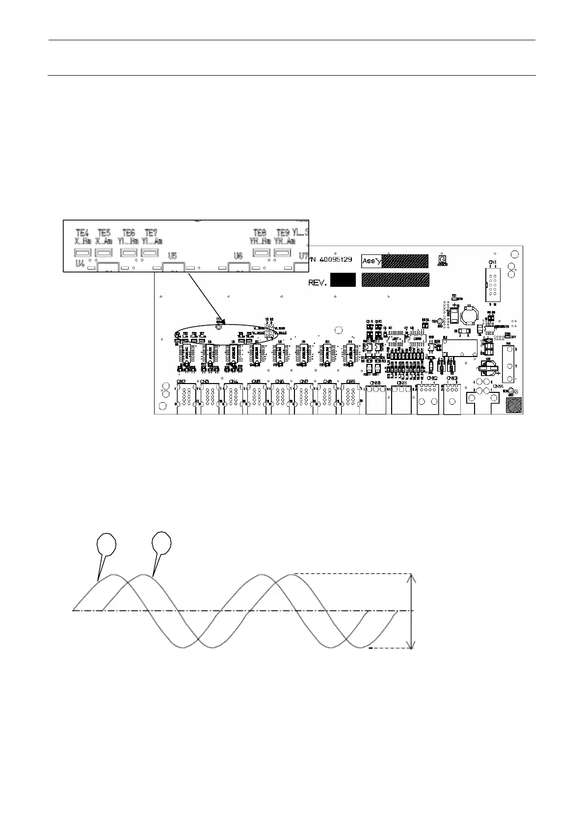
3) Use the test pins on the MAGNET IC SCALE board (part No. 40095130) shown in the figure
below.
Note) Detach or attach the cover and probe with the power turned OFF.
Figure 1-2-3-1
4) For every axis, connect the probe of the oscilloscope to the GND terminal "GND (TE3)", "XA
(TE5)", "YLA (TE7)" or "YRA (TE9)" respectively to measure the voltage waveform. At this
time, observe the amplitude of the A-phase and B-phase waveforms shown on the
oscilloscope to make sure that the P-P value is 2.0V±0.5V in the entire area.
A
B
Each amplitude
1.5 to 2.5Vpp
(In the recommended
mounting status)
Figure 1-2-3-2
5) If the P-P value is not 2.0V±0.5V, loosen the screw securing the sensor (SL6040892TN (M
and L board specifications), SL6041092TN (XL board specifications) for the X-axis and
SM6030502TN, SL6041092TN for the Y-axis shown in the figure below).
 Loading...


