Rev. 2.0
Maintenance Guide
9-12
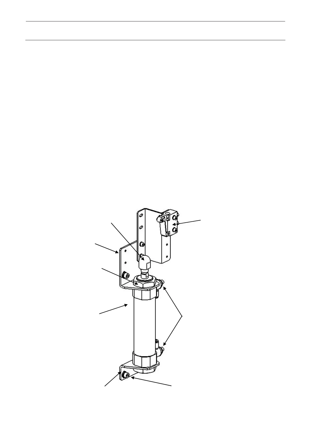
9-1-8. Replacing the Electric Bank Support Cylinder (Optional Replacement Table)
1) Turn OFF the compressed air to the machine main unit and disconnect the air tubes from the
speed controller.
2) Remove the upper and lower cylinder mounting nuts and the lower hexagon socket head cap
bolts (M6×12: 2 locations) to detach the cylinder and lower bracket.
3) Attach the speed controller and lifter shaft head to a new cylinder.
Tighten the lifter shaft head until the cylinder rod is in contact with the edge of the bolt hole.
4) Reassemble the components in the reverse order of disassembly.
5) Turn ON the compressed air to the machine main unit and adjust the cylinder speed.
Adjust the cylinder speed to that of the cylinder, which has not been replaced, through visual
check.
6) When the machine with the L and M specifications has the mechanical/electric replacement
table specifications, adjust the mechanical valve position after mounted on the FL and RR
sides. (For details about how to adjust the valve position, see section 9-1-1, Replacing the
Mechanical Valve.)
<L and M Specifications>
SL6061292TN
SCREW M6 L=12
40094347
CYLINDER CM2B40-75
40093842
LIFTER_SHAFT_HEAD
PC015203000
SPEED CONTROLLER
Cylinder mounting nut
40111180
CYLINDER_BR_U
40093841
CYLINDER BR
The mechanical valve for
the drive cylinder up/down
is provided only on the FL
and RR sides of the
machine with the
mechanical/electric
replacement table
specifications.
 Loading...


