Rev. 2.0
Maintenance Guide
14-33
14-6. Z-θ Unit
The Z-θ unit is composed of an AC servo amplifier that drives the Z/θ-axes.
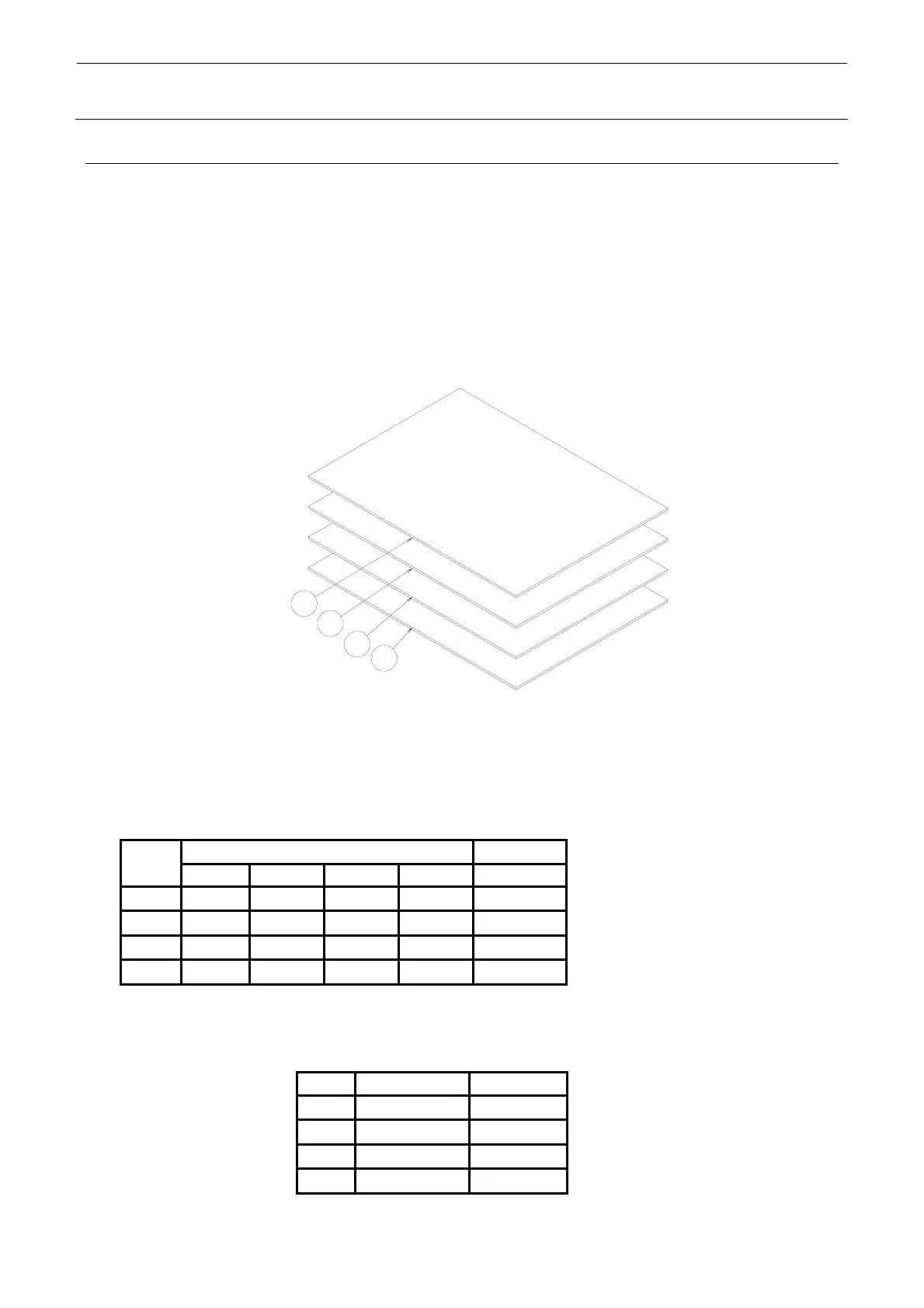
14-6-1. Structure of Z-θ Unit
The servo amplifier for the Z/θ-axis is a 4-axis integrated servo amplifier that one amplifier board
can drive the 4 axes.
The servo amplifier board for the Zθ-axis is mounted in the head unit. Actually, four boards are
mounted in the vertical direction.
Three boards are mounted only in the KE-3010 (f is not mounted).
Figure 14-6-1-1 shows the relationship among each motor and servo amplifier.
Figure 14-6-1-1 Structure of Z/θ Unit
∗ Motor outputs
Each Z-axis: 30W
Each θ-axis: 15W
Table 14-6-1-1 Z/θ-Unit Layout Relational Diagram
Axis No. on amplifier
Symbol
Axis No. 1 Axis No. 2 Axis No. 3
Axis No. 4
Part No.
c
L2
θ-axis
L2 Z-axis
L1 θ-axis
L1 Z-axis
40044535
d
L4
θ-axis
L4 Z-axis
L3 θ-axis
L3 Z-axis
40044535
e
L6
θ-axis
L6 Z-axis
L5 θ-axis
L5 Z-axis
40044535
4
Not used Not used
IC θ-axis
IC Z-axis 40044535
For the Zθ-servo amplifier, set the rotary switch (CS1) appropriately according to the board.
Table 14-6-1-2 Z/θ-Unit Layout Relational Diagram
Symbol Servo amplifier
SW set value
c
L1, 2 Z/θ-axis
0
d
L3, 4 Z/θ-axis
1
e
L5, 6 Z/θ-axis
2
4
IC Z/
θ-axis
3
1
2
3
4
← This board is not mounted in
the KE-3010.
← This board is not mounted in
the KE-3010.
 Loading...


