Rev. 2.0
Maintenance Guide
1-1
[1] X-Y UNIT
1-1. Replacing the Servomotor
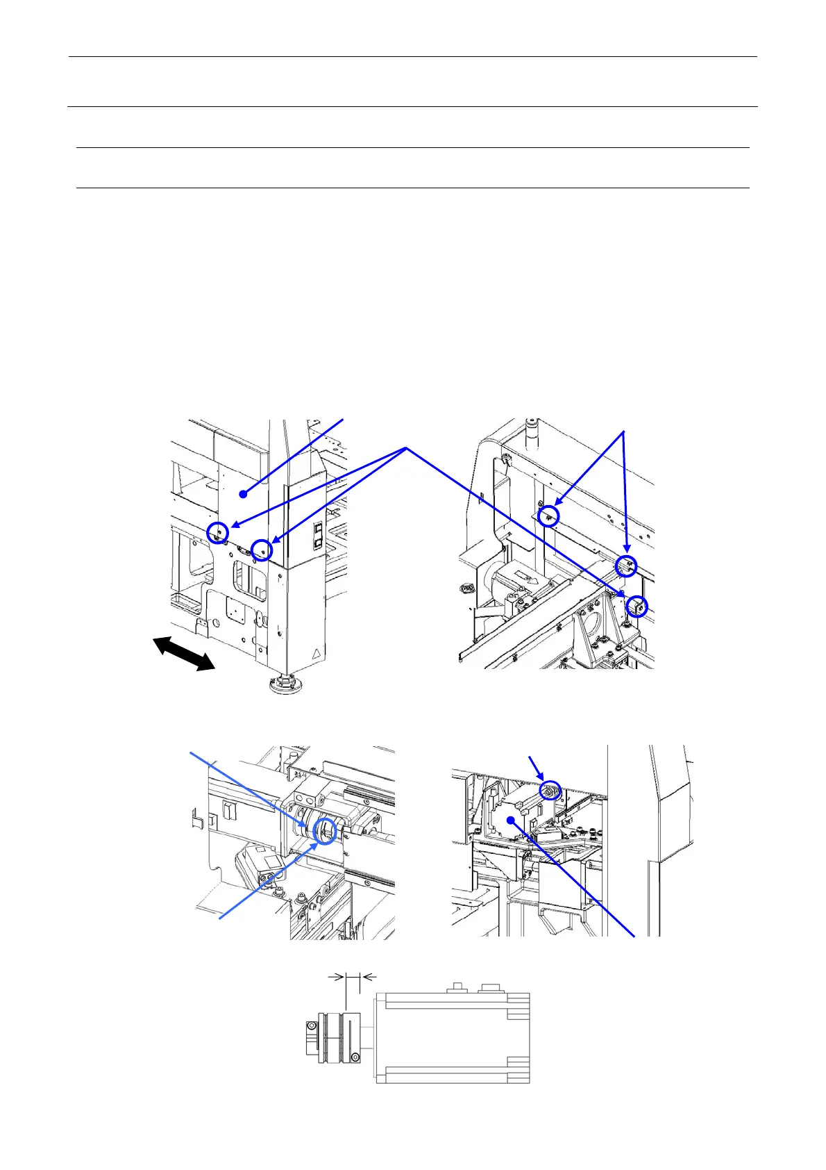
1-1-1. Replacing the X-Motor
<M and L board specifications>
1) Remove the SL6061292TN, NM6060001SC to detach the COVER_SUL_F_M.
2) Loosen the COUPLING_X_screw (do not remove the screw at this time) and disconnect the
connector of the SERVO MOTOR 750W cable.
3) Remove the SL6062042TN and replace the SERVO MOTOR 750W.
4) Reassemble the components in the reverse order of disassembly.
∗ The clearance between the COUPLING and motor is 8 mm.
The tightening torque of the COUPLING_X_screw is 3.4 N⋅m. (Figure 1-1-1-4)
Carefully check the motor orientation.
Figure 1-1-1-1 Removal of Cover of Machine with M and L Board Specifications
REAR
FRONT
COVER_SUL_F_M
SL6061292TN (
Inside of left side of machine
3)
NM6060001SC (×2)
8
Figure 1-1-1-4
Figure 1-1-1-3
SERVO MOTOR 750W
SL6062042TN
4
Figure 1-1-1-2
COUPLING_X_screw
COUPLING_X
 Loading...


