Rev. 2.0
Maintenance Guide
9-10
9-1-6. Replacing the Cylinder for Drive Cylinder Unit Up/Down (Specifications
Common to Optional Electric and Mechanical Replacement Tables)
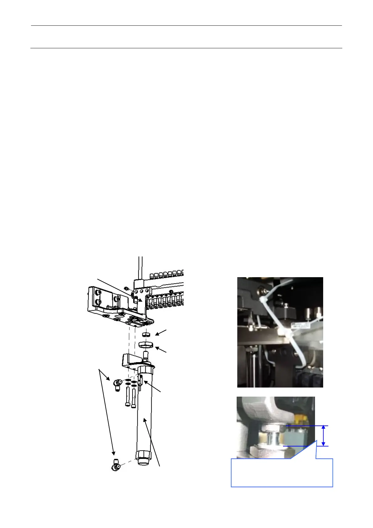
1) Turn OFF the compressed air to the machine main unit and disconnect the air tubes from the
speed controller.
2) Raise the driver cylinder unit upward and secure it to the left and right bank supporters with
tie-up bands.
3) Remove the nuts 1 and 2 to detach the cylinder.
4) Attach the speed controller and sensor (FL and RR only) to a new cylinder.
5) Turn the knob on the speed controller four rotations from its fully open position toward the
“close” side, and then lock it firmly.
6) Attach the cylinder with the nuts 1 and 2. For details about nut 2 assembly position, see the
Figure below.
7) Remove the tie-up bands secured to the bank supporters to check that the drive cylinder unit
falls down by its own weight.
8) Connect the air tubes to the speed controller and turn ON the compressed air to the machine
main unit.
9) Adjust the sensor position after the power to the machine has been turned ON. Adjust the
sensor position so that the sensor is turned ON when the drive cylinder moves up to its upper
limit. (Secure the sensor position at the intermediate position of the sensor ON range.)
Distance between bottom of
DRV_SYL_SPT and top of
cylinder bolt: 20 mm
Secure the drive cylinder with
tie-up bands.
Nut 1
Nut 2
PC015203000
SPEED CONTROLLER
Sensor
40071364
40094348
-