Rev. 2.0
Maintenance Guide
1-32
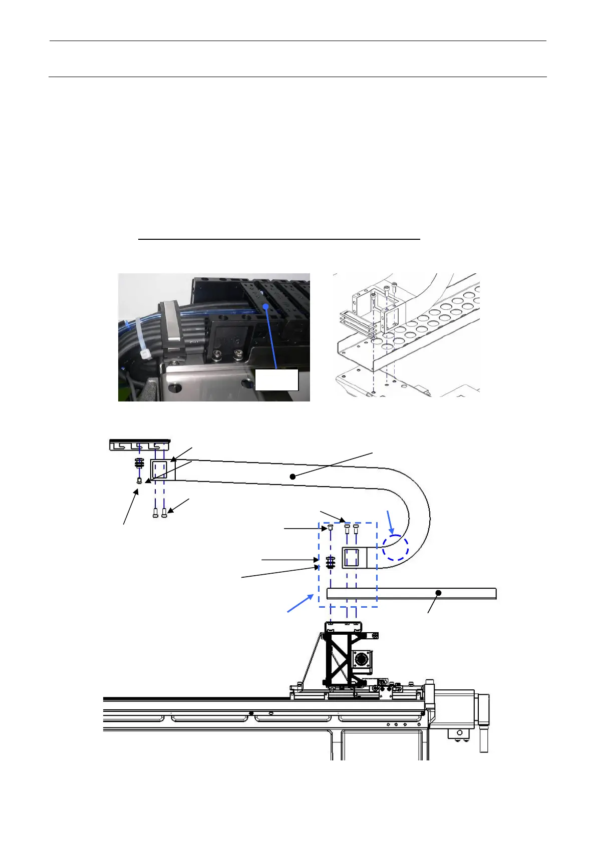
1-5-2. Replacing the Y-Axis Cableveyor
<M and L board specifications> Y_CABLE_BEAR_M (Part No.: 40110452)
Y_CABLE_BEAR_L (Part No.: 40111993)
1) Remove the hexagon socket head cap bolt (M6×16) to detach the Y_CABLE_BEAR from
the CB_BRACKET and Y_CB_SUPPORT.
2) Remove the round screw (M6×10) to detach the FC_SUPPORT_Y, FC_SUPPORT_Y_V2
and FC_RUBBER_Y.
3) Remove the arm of the Y-axis cableveyor, take out the cables, and replace the cableveyor.
4) Reassemble the components in the reverse order of disassembly. At this time, pay special
attention
so that the cables inside the cableveyor are not entangled.
Additionally, move the Y-axis to the foremost position and push the cables inside the
Y-cableveyor by hand to check that they are flexible.
Y_CABLE_BEAR_L (40111993)
Y_CABLE_BEAR_M (40110452)
CB_BRACKET (40113929)
FC_SUPPORT_Y_V2 (40110219)
FC_RUBBER_Y (40098052)
Round screw
(M6 × 10)
Hexagon socket head cap bolt (M6 × 16)
FC_SUPPORT_Y_V2 (40110219)
Y_CB_SUPPORT (40114009)
B
A
Hexagon socket head cap bolt (M6 × 12)
Hexagon socket head
cap bolt (M6 × 8)
Part B
Part A
Arm
Figure 1-5-2-1 Y-Axis Cableveyor (M and L Board Specifications)
 Loading...


