Rev. 2.0
Maintenance Guide
14-40
14-7-3-2. Setting the Stepping Motor Driver for Support Table/Auto Width
Adjustment
<Adjustment Procedure for Machines not Applicable to EN>
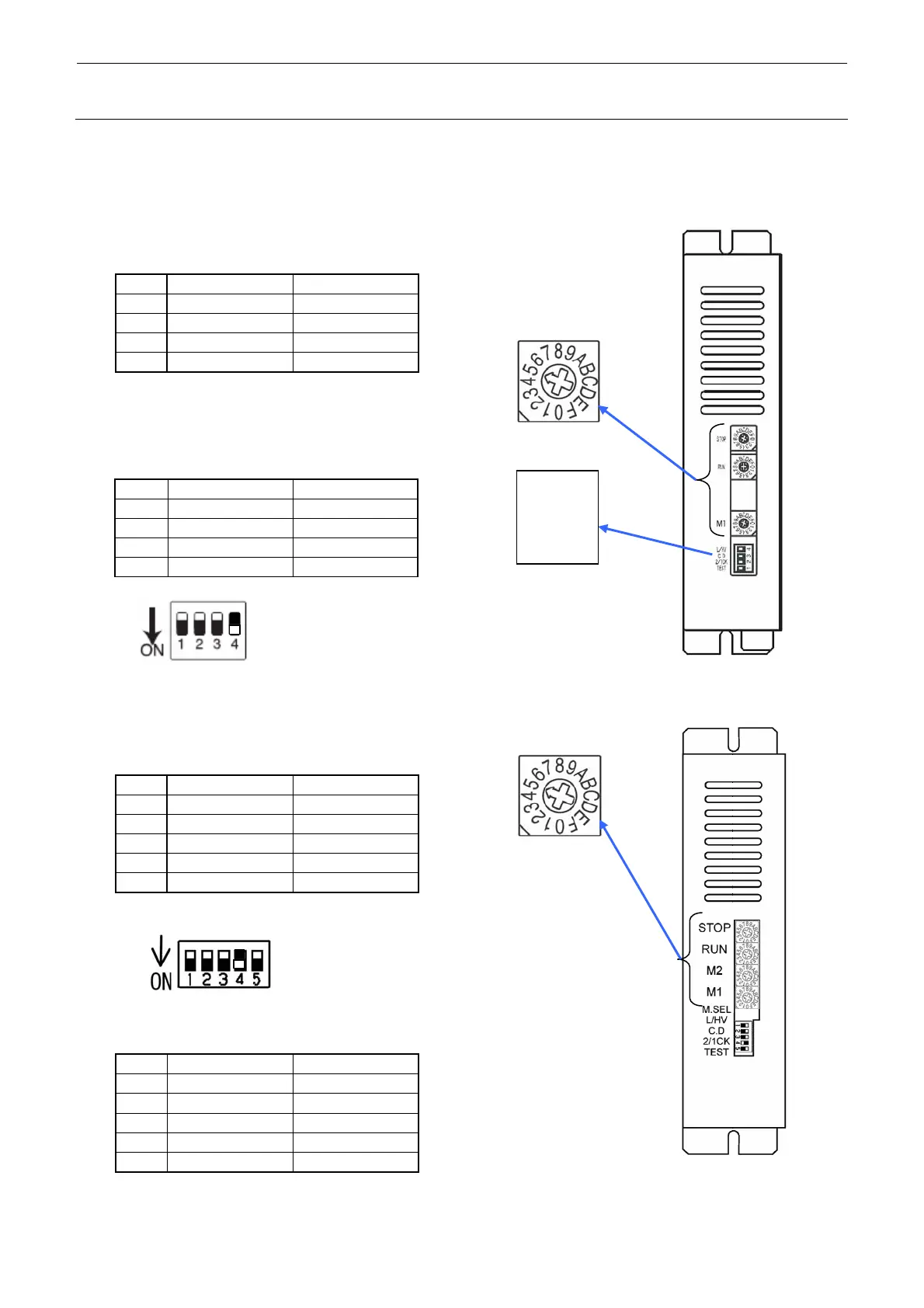
c Set the rotary switches to the values in the table below.
Table 14-7-3-2-1 Setting the Stepping Driver
No. Switch Settings
1 STOP(BU) 9
2 STOP(AWC) 5
3 RUN C
4 M1 0
d Set the DIP switches to the
values in the table below.
Table 14-7-3-2-2 Setting the Stepping Driver
No. Switch Settings
1 TEST OFF
2 2/1CK OFF
3 C.D OFF
4 L/HV ON
<Adjustment Procedure for Machines Applicable to EN>
c Set the rotary switches to the values in the table below.
Table 14-7-3-2-3 Setting the Stepping Driver
No. Switch Settings
1 STOP(BU) 9
2 STOP(AWC) 5
3 RUN C
4 M2 0
5 M1 0
d Set the DIP switches to the values in the table below.
Table 14-7-3-2-4 Setting the Stepping Driver
No. Switch Settings
1 TEST OFF
2 2/1CK OFF
3 C.D OFF
4 L/HV ON
5 M.SEL OFF
Switch lever positions
When the switch is flipped down, it is
turned ON. On the contrary, when the
switch is flipped up, it is turned OFF.
Figure 14-7-3-2-1 DIP-SW
Rotate the rotary switch
so that the arrow points to
h
ir
v
l
.
STOP
RUN
L/HV
C.D
2/1CK
TEST
M1
Switch lever positions
When the switch is flipped down, it is
turned ON. On the contrary, when the
switch is flipped up, it is turned OFF.
Figure 14-7-3-2-2 DIP-SW
 Loading...


