Rev. 2.0
Maintenance Guide
15-5
<Procedure>
1) Fix the sensor bracket AWC c at the right and left positions on the movable rail with screws
d.
2) Mount the support pin sensor (emission side) e and the support pin sensor (receiving side) f
on the sensor bracket AWC, using screws g. Turn ON the power, and adjust the position of
the sensors so that their optical axes are aligned.
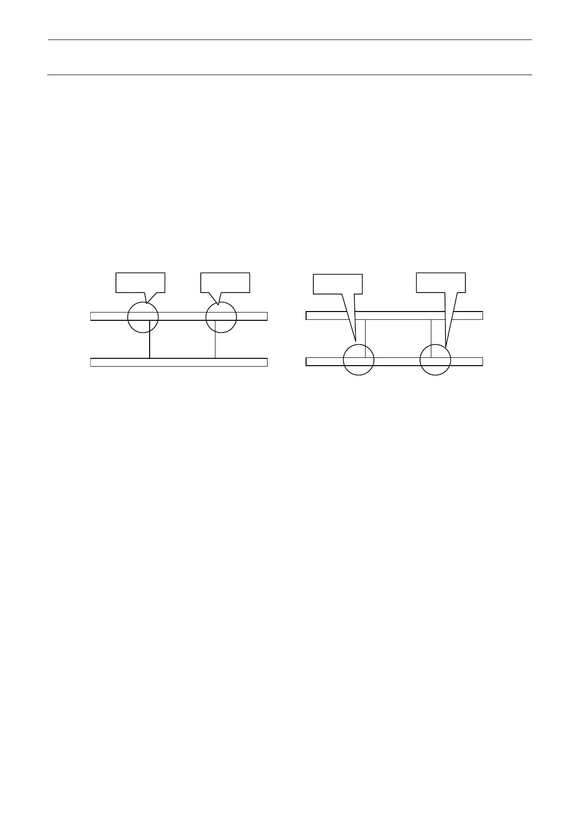
The support pin sensors must be mounted on the movable-side rail.
The mount position when viewed from the mounter front differs depending on the machine
reference (front reference, rear reference).
Figure 15-3-1-2
M、L
M、L
投光受光
投光
受光
手前基準 奥基準
Light
receivin
Light
receivin
Light
emission
Light
emission
M, L, XL
M, L
Front reference Rear reference
 Loading...


