4-13. Replacement and adjustment of head ascent/descent sensor
Detach the XF cover and the X cover, and replace the sensor.
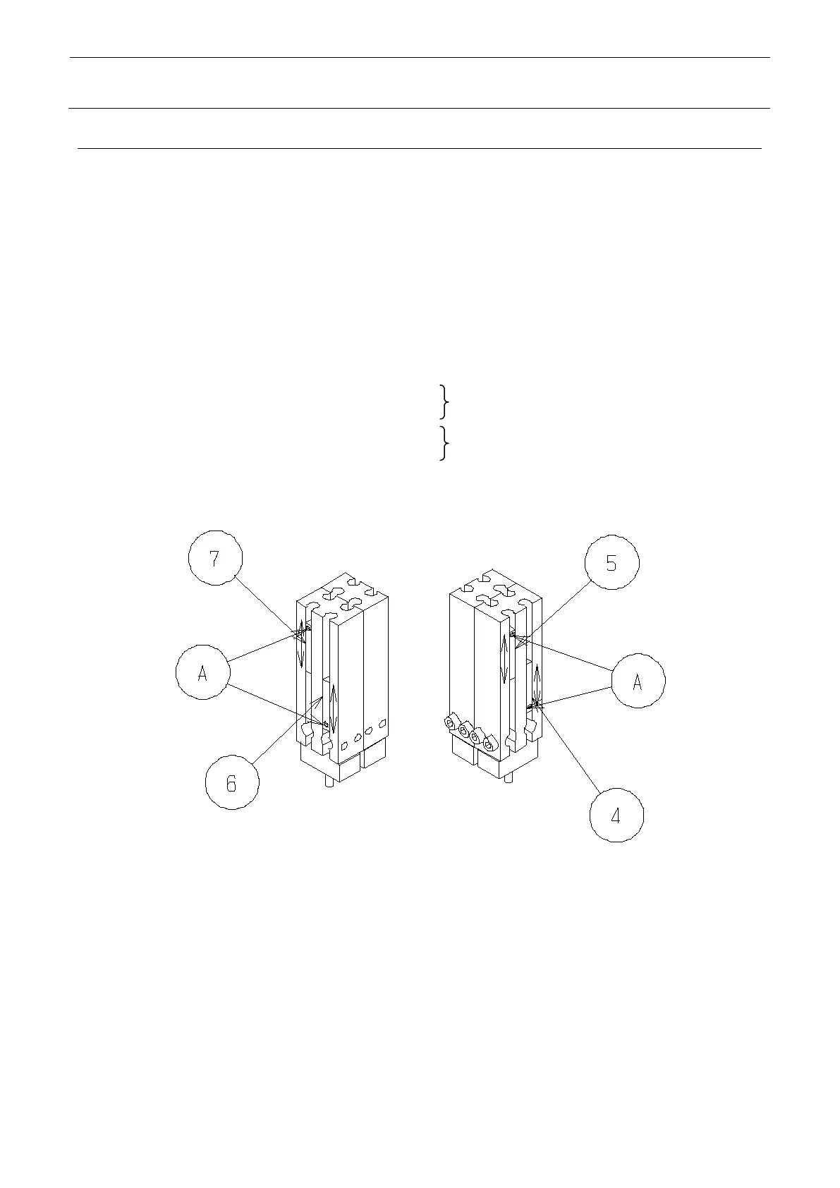
Loosen the sensor mounting screw A, and replace the sensor.
At the same time, replace and , and and , which make a set for each pair,
When the replacement is finished, make adjustment of described below.
Adjust the sensor arrangement so that LED of ascent sensors and lights up at the stroke
end on the cylinder pull-in side, and LED of descent sensors and lights up at the stroke end
of the cylinder push-out side.
The sensors have a detection range of approximately 2.5 mm, and therefore, make adjustment
so that detection will be made at the center of that range.
Head R descent sensor (part No.: 40045127)
Head R ascent sensor (part No.: 40045127)
Head L descent sensor (part No.: 40045126)
Head L ascent sensor (part No.: 40045126)
Two pieces (making one set)
Two pieces (making one set)
4-13
 Loading...


