7-10
7-10. Replacement of shuttle ejector
Detach the X front cover and replace the ejector.
When the replacement is finished, make adjustment as described below.
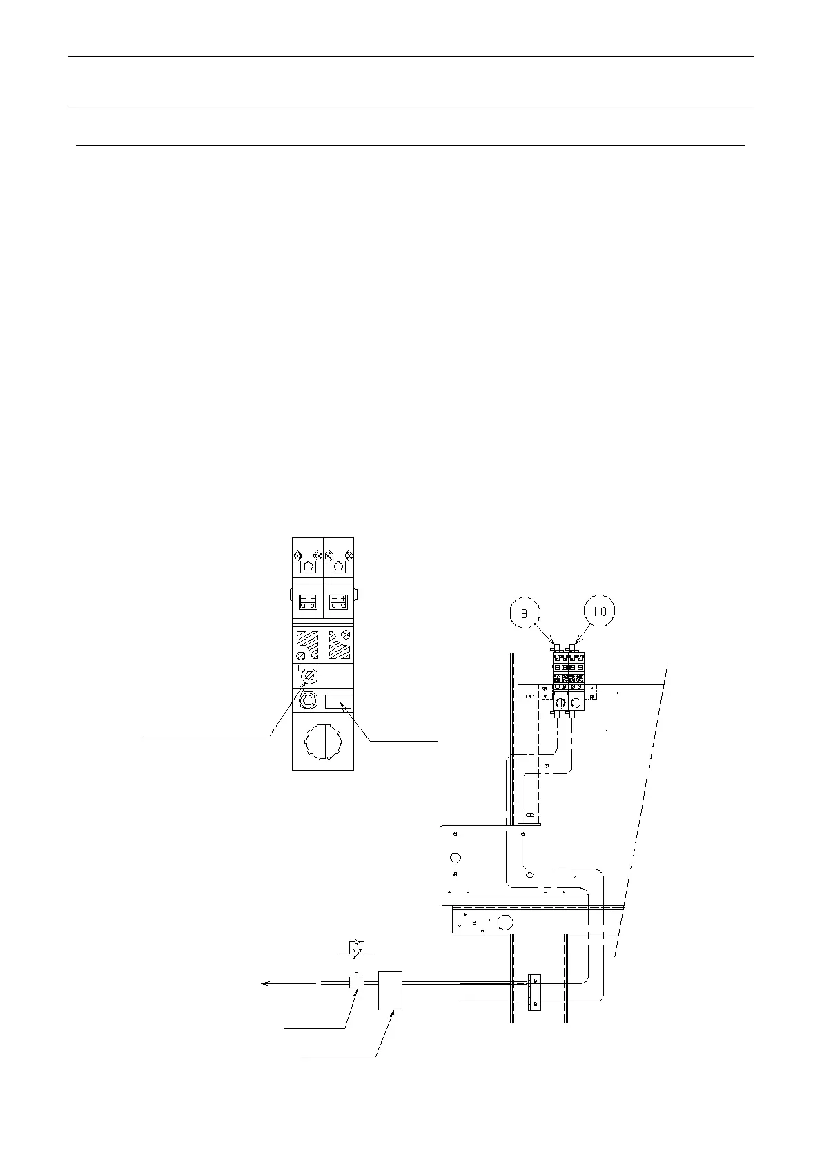
Set the air pressure to 0.5 MPa.
Insert a speed controller and a manometer between the shuttle picking pad and the ejector, and
connect them.
Using “4. Shuttle Vacuum” of test mode, execute vacuuming without blocking the pad of shuttle.
Adjust the speed controller so that the vacuum pressure will be −0.4 kgf/cm (−39kPa).
When the above adjustment is finished, adjust the pressure setting trimmer so that the position
for the LED that is just going to be lit up will be identified.
Then adjust the speed controller to set the vacuum pressure to −0.35 kgf/cm (−34kPa), and
ensure that the LED of pressure setting trimmer is not lighting.
If the LED keeps lighting, set the vacuum pressure back to −0.4 kgf/cm, and try again to repeat
the adjustment.
Make adjustment of the same procedure both for L and R.
SPAD L ejector (part No.: 40045158)
SPAD R ejector (part No.: 40045159)
 Loading...


