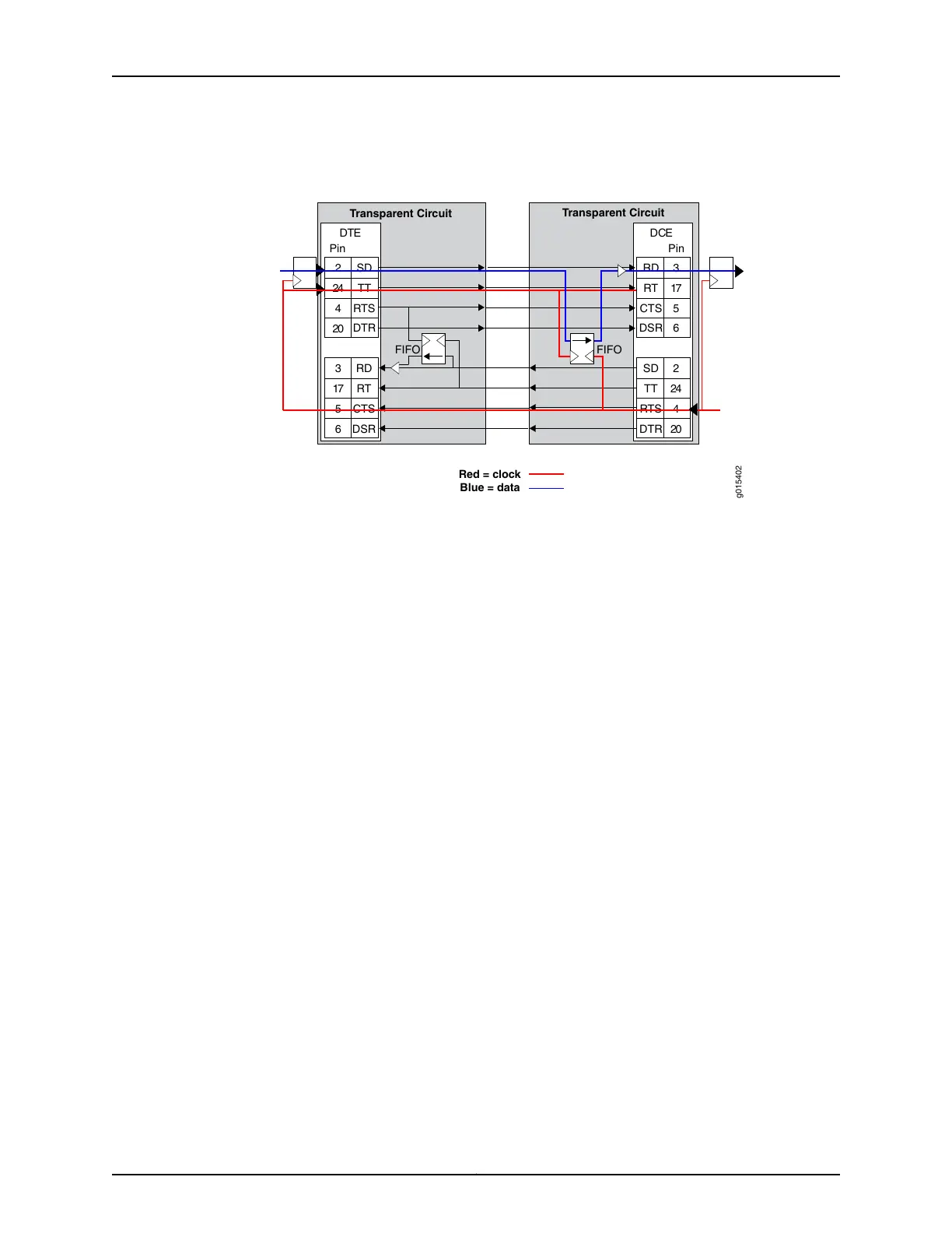
Figure 5: Clock and Data Paths with Transparent Phase-Correction FIFO
Buffers
Transparent Circuit
Transparent Circuit
DTE DCE
g015402
RD
RT
CTS
DSR
2
24
4
20
SD
TT
RTS
DTR
3
17
5
6
2
24
4
20
SD
TT
RTS
DTR
3
17
5
6
RD
RT
CTS
DSR
Red = clock
Blue = data
Pin Pin
FIFO FIFO
Like in TRANS encoding, you can use the 16 bit phase correction FIFO in TRANS 8 encoding
to accommodate the problems that can be caused by the high latency in the circuit
whether or not the remote DCE device can accept TT input or not.
When the customer DCE device can support the TT signal returned by the DTE, the phase
correction FIFO is not needed. The DCE transmit clock (ST) is sampled and carried
downstream to the DTE, where it is used to generate the upstream data that is sent back
to the customer DCE. This clock data is also sent as the DTE transmit clock (TT) to travel
along with the data in phase. When these signals get back to the customer DCE device,
they are still in phase (same delay through the network), so the customer DCE can use
the TT signal to recover the transmit data on the SD lead.
Consider a scenario in which the customer's upstream DCE does not use the TT signal
for capturing upstream data, and instead uses the ST clock. Here, due to the latency of
the ST clock traveling downstream and the time taken for the return trip of the data, it
is difficult to ensure error-free data transport. In such a scenario, you can use phase
correction FIFO to ensure error-free data transport.
The SD or TT clock and data signals get back to the upstream CTP device, where the
data is clocked into the FIFO using the TT clock, which is in phase. This data is clocked
out of the FIFO using the upstream ST clock, and the data is realigned to be in phase with
the ST clock.
See Also Transparent Encoding Applications and Support Overview on page 12•
• How Basic Transparent Encoding Works on page 13
• Using Send Timing (ST) Clocking for Higher Speed Circuits with Transparent Encoding
on page 16
• Configuring Transparent Encoding for CTP Bundles (CTP Menu) on page 60
• Configuring Transparent Encoding for CTP Bundles (CTPView) on page 58
15Copyright © 2018, Juniper Networks, Inc.
Chapter 1: Overview of CTP Bundles
 Loading...