•
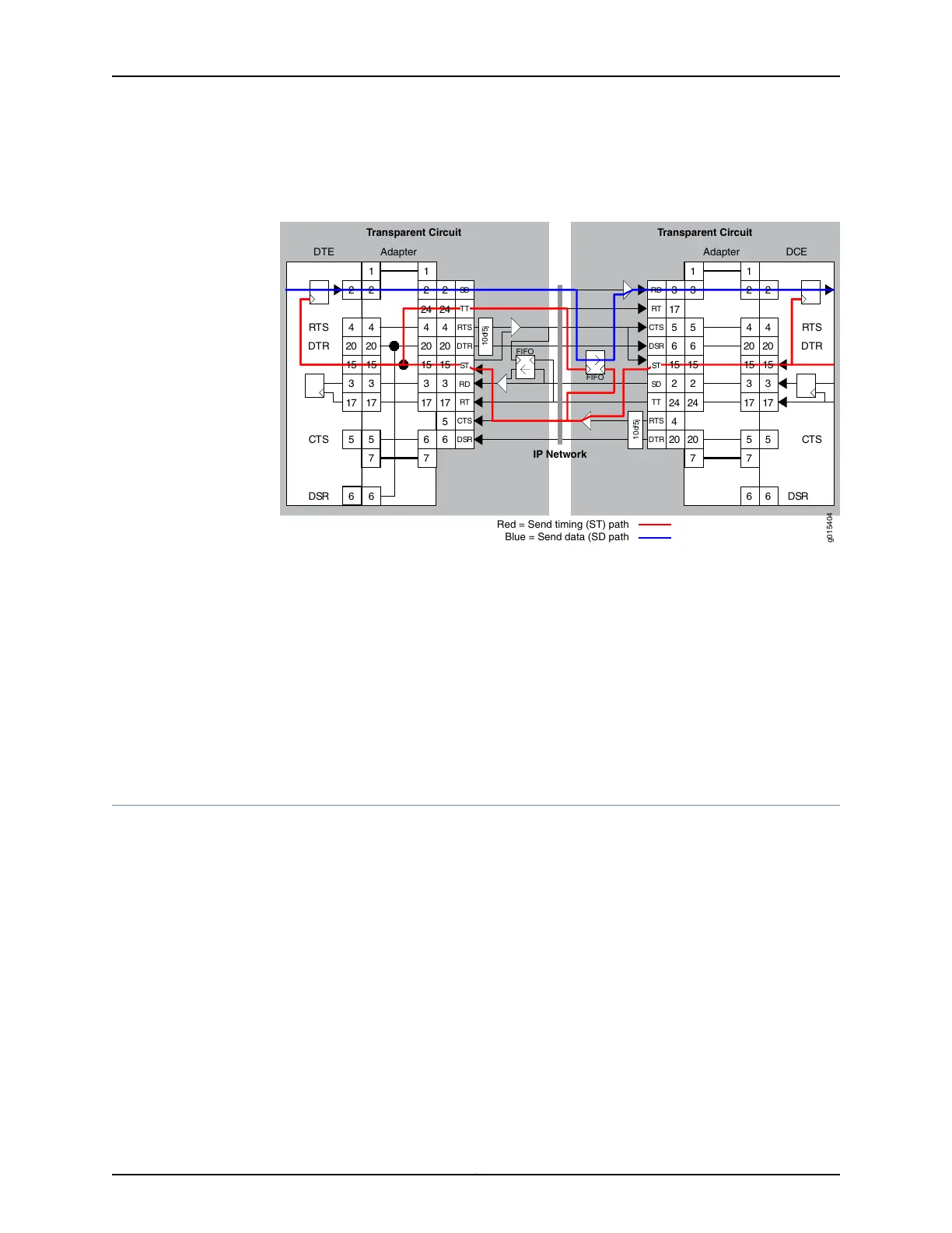
At the DTE, that signal is placed onto the ST lead, which is configured as an output.
Figure 7: Transparent Encoding Using ST Clocking
IP Network
g015404
Red = Send timing (ST) path
Blue = Send data (SD path
3
17
4
5
7
3
17
4
6
6
20
7
1 1
20
2
24
5
20
7
3
17
4
5
6
20
7
1 1
6
3
17
4
5
6
20
DTR
RTS
RD
DSR
RT
CTS
2
24
17
4
5
6
20
SD
DTR
TT
RTS
DSR
RT
CTS
Transparent Circuit
10d/5j
10d/5j
DTE
3
17
4
5
6
20DTR
DSR
RTS
CTS
DCE
3
17
4
5
6
20
RTS
CTS
DTR
DSR
Adapter Adapter
2
24
15
2
15
3 2
1515
2
24
SD
3
RD
1515
2
15
2
15
FIFO
FIFO
ST ST
TT
Transparent Circuit
When you configure transparent encoding to use the ST lead instead of RTS/CTS, you
can specify whether or not ST is an input lead.
See Also Transparent Encoding Applications and Support Overview on page 12•
• How Basic Transparent Encoding Works on page 13
• Using Phase-Correction FIFO Buffer with Transparent Encoding on page 14
• Configuring Transparent Encoding for CTP Bundles (CTP Menu) on page 60
• Configuring Transparent Encoding for CTP Bundles (CTPView) on page 58
TDM/TDC Encoding Overview
The time domain correlation (TDC) feature uses time division multiplexing (TDM) to
interleave multiple data types on serial ports so that the CTP device can bond two circuits
into a single data stream. Doing so allows the CTP device to carry two independent data
streams on the same path through the IP network . Out of each set of 32 bits in the IP
data stream, you can designate a certain number of bits for TDM functions.
The TDM/TDC feature is commonly used for telemetry applications, and is supported
on CTP2000 serial interfaces.
How TDM Interleaving Works
When TDM is not being used, all 32 bits in the IP data stream transport serial data on a
port. For example, Figure 8 on page 18 shows all 32 bits being allocated to local serial
port data as indicated with the D.
17Copyright © 2018, Juniper Networks, Inc.
Chapter 1: Overview of CTP Bundles
 Loading...