Table 13: Chassis Viewer for EX4300 Switches (continued)
DescriptionField
The Console port (RJ-45) is used to connect the switch to a management console or to a console
server.
Console port
Indicates the USB port for the switch.
NOTE: We recommend that you use USB flash drives purchased from Juniper Networks for your
EX Series switch.
USB port
Mouse over the fan tray icons to display name, status, and description information.Fan tray
Mouse over the power supply icons to display name, status, and description information.Power supplies
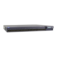
The rear panel of a 24-port and a 48-port EX4300 switch has four (built-in) 40-Gigabit QSFP+
ports, and the rear panel of an EX4300-32F switch has two (built-in) 40-Gigabit QSFP+ ports, in
which you can install QSFP+ transceivers. Mouse over the ports to view the details of the ports.
After you install a transceiver in the port, the following colors denote the interface status:
•
Green—Interface is up and operational.
•
Yellow—Interface is up but is not operational.
•
Gray—Interface is down and not operational.
For QSFP+ ports, the interfaces appear dimmed if no transceiver is inserted. The chassis viewer
displays Transceiver not plugged in when you mouse over the port.
When a QSFP+ port is configured as a Virtual Chassis Port (VCP), the following colors denote the
VCP status:
•
Green—VCP is up and operational.
•
Yellow—VCP is up but is not operational.
•
Gray—VCP is down and not operational.
PIC 1 slot
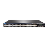
Table 14: Chassis Viewer for EX4500 Switches
DescriptionField
Front View
In the image, the colors listed below denote the interface status:
•
Green—Interface is up and operational.
•
Yellow—Interface is up but is nonoperational.
•
Gray—Interface is down and nonoperational.
Mouse over the interface (port) to view more information.
For a Virtual Chassis configuration, select the switch to view the interface status.
If an SFP+ uplink module is installed in the switch, mouse over the interface (ports) on the
module for more information.
For SFP and SFP+ ports, the interfaces appear dimmed if no transceiver is inserted. The chassis
viewer displays Transceiver not plugged-in when you mouse over the port icon.
Interface status
Copyright © 2017, Juniper Networks, Inc.20
J-Web Application Package User Guide for EX Series Switches, Release 14.1X53-A1
 Loading...