Connections
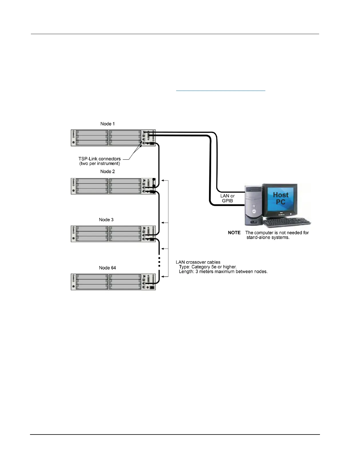
Connections for an expanded system are shown in the following figure. As shown, one instrument is
optionally connected to the computer using the GPIB or LAN interface. Details about these computer
communication connections are described in Remote communications interfaces (on page 2-6).
All the instruments in the system are connected in a sequence (daisy-chained) using LAN crossover
cables.
Figure 136: TSP-Link connections to multiple instruments
Initialization
Before a TSP-Link
®
system can be used, it must be initialized. For initialization to succeed, each
instrument in a TSP-Link system must be assigned a different node number.
Assigning node numbers
At the factory, each Series 3700A instrument is assigned as node 1. The node number is stored in
nonvolatile memory and remains in storage when the instrument is turned off. You can assign a node
number to a Series 3700A using the front panel or by using a remote command. Note that there can
only be 32 physical nodes, but you can assign node numbers from 1 to 64.

 Loading...


