Section 3: Instrument description Series 3700A System Switch/Multimeter Reference Manual
3-4 3700AS-901-01 Rev. D/June 2018
The bottom left line of the display contains the DMM attribute symbols. The symbols that appear are
dependent on whether the attribute exists for the selected function. The following table indicates the
DMM attribute symbols that may appear on the front panel. If the symbol has a value associated with
it, the third column in the table indicates the value definition.
Front-panel DMM attribute
AUTO or n, where n equals the range
n, where n equals the NPLC
+ for ON, 1 for ONCE, or 0 for OFF
+ for a limit enabled or – for limits disabled
n, where n indicates the threshold
n, where n indicates the aperture setting
simulated reference junction
internal reference junction
external reference junction
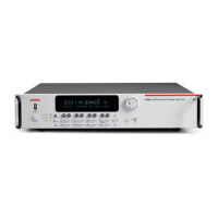
Turn the navigation wheel to scroll to a menu option or to change the value of the
selected numeric parameter. Pressing the navigation wheel has the same functionality
as pressing the ENTER key.
When changing a multiple character value, such as an IP address or channel pattern
name, press the navigation wheel to enter edit mode, rotate the navigation wheel to
change the characters value as needed, but do not leave edit mode. Use the CURSOR
keys to scroll to the other characters and use the navigation wheel to change their value
as needed. Press the ENTER key when finished changing all the characters.
Power switch. The in position turns the Series 3700A on (I); the out position turns it off
(O).

 Loading...