11.5
Section 11
Reassembly
11
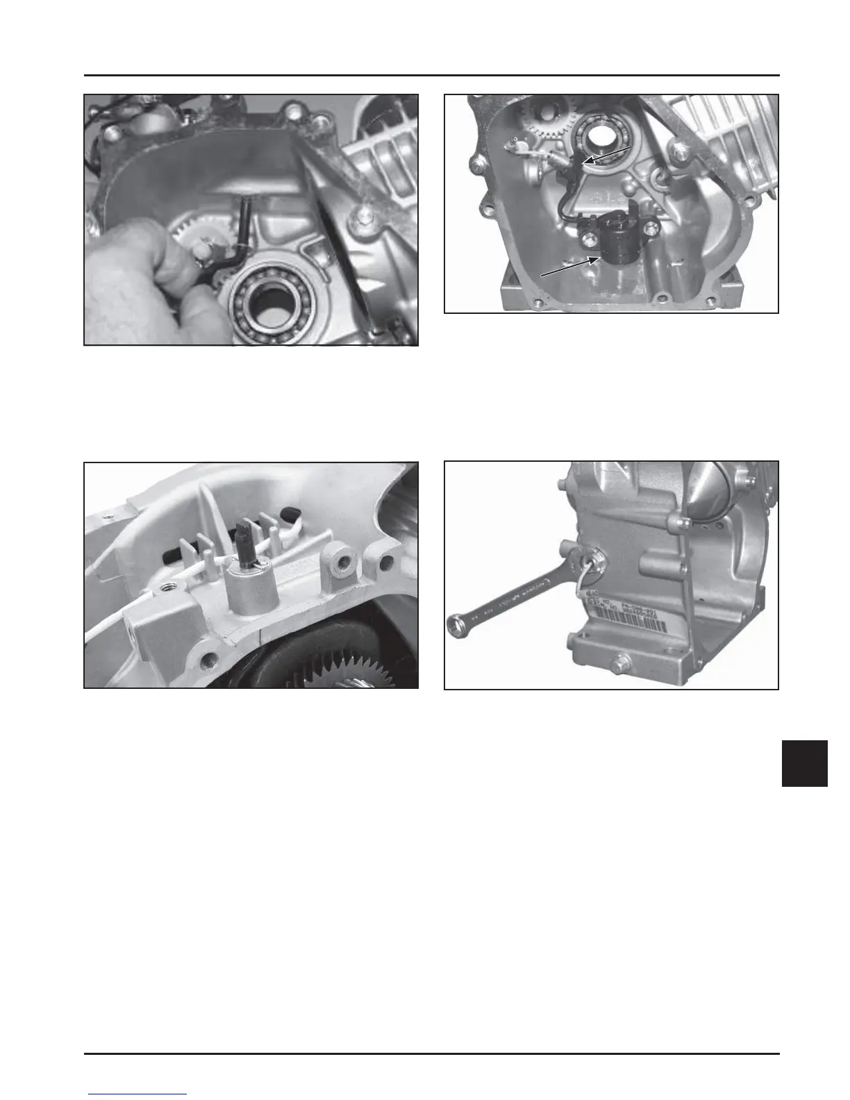
Figure 11-18. Oil Sentry™ Float Switch Mounting.
2. Route the wire lead grommet assembly through
the cranksha housing. See Figure 11-18.
3. Install the nut on the grommet assembly external
stud and torque to 10 N·m (89 in. lb.). See Figure
11-19.
Grommet
Assembly
Oil Sentry
TM
Float Switch
Figure 11-19. Oil Sentry™ Wire Lead Grommet
Mounting.
Install Crankshaft
1. Carefully slide the fl ywheel end of the cranksha
through the main ball bearing and seal. See
Figure 11-20.
Figure 11-16. Installing Governor Shaft.
8. Install the second fl at washer onto the sha .
Position the sha so the fl at index end of the sha
faces to the le (9 o'clock position) and insert the
hitch pin from the PTO side. See Figure 11-17.
Figure 11-17. Installing Thrust Washer and Hitch
Pin.
Install Oil Sentry™ System
1. Mount the Oil Sentry™ fl oat switch into the
crankcase housing using two M6x18 hex fl ange
screws and torque to 8 N·m (71 in. lb.). See
Figure 11-18.
 Loading...


