11.12
Section 11
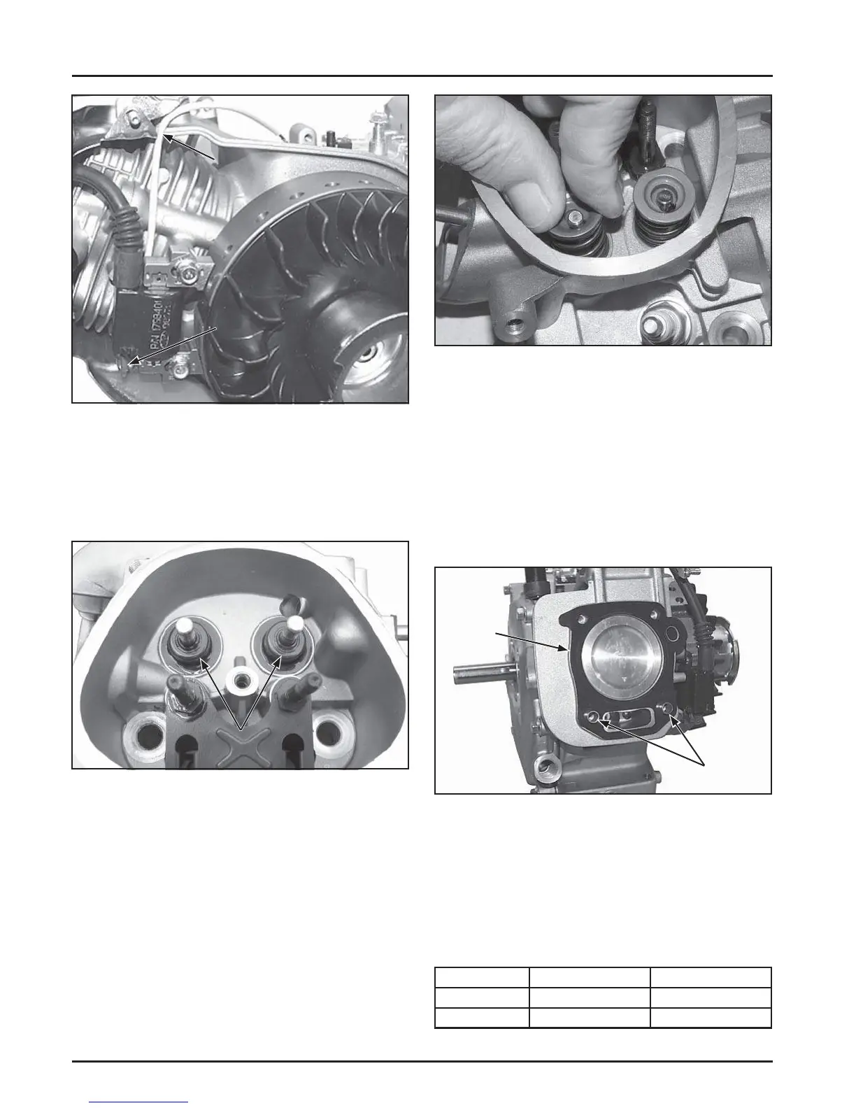
Reassembly
Figure 11-45. Installing Valve Retainers.
Install Cylinder Head
1. Check to make sure there are no nicks or burrs
on the sealing surfaces of the cylinder head or
crankcase.
2. Rotate the cranksha to position the piston at
TDC on the compression stroke.
3. Install the dowel pins into the recesses around the
lower cylinder head bolt holes. See Figure 11-46.
Head
Gasket
Dowel Pins
Figure 11-46. Installing Dowel Pins and New Head
Gasket.
4. Install a new cylinder head gasket.
5. Install the cylinder head and start the four hex
fl ange screws. Torque the screws in increments
using the sequence shown. See Figure 11-47.
Torque the hex fl ange screws following the table.
Model Initial Torque Final Torque
CH270 12 N·m (106 in. lb.) 24 N·m (212 in. lb.)
CH395,CH440 18 N·m (159 in. lb.) 36 N·m (319 in. lb.)
Figure 11-43. Connect Kill Wire To Module.
Assemble Cylinder Head
1. Install the valves into their respective positions.
2. Install new valve seals on the stem of the valves.
See Figure 11-44.
Module Terminal
Route Wire Here
Figure 11-44. Valve Stem Seals.
NOTE: The engine utilizes valve stem seals on the
valves. Always use a new seal when valves
are installed in the cylinder head. Never
reuse old seals.
3. Install the valve springs and retainers into their
respective locations in the cylinder head. Support
the valve heads from underneath. Using hand
pressure, compress each valve spring and slide
each retainer onto the valve stem to lock in place.
See Figure 11-45.
Valve Seals
 Loading...


