11.9
Section 11
Reassembly
11
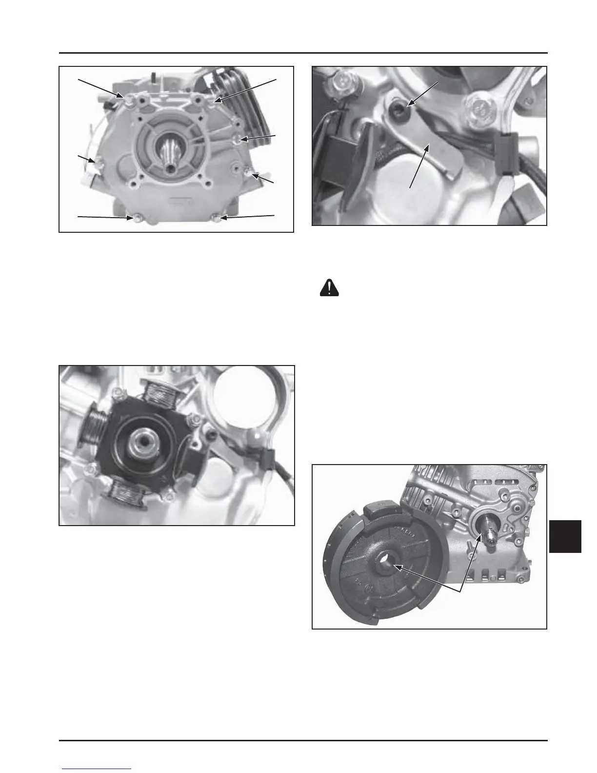
Clean Bore and
Shaft Surfaces
Figure 11-34. Install Bracket and Torque Screw.
Install Flywheel
WARNING: Damaging Crankshaft and
Flywheel Can Cause Personal Injury!
Using improper procedures to install the fl ywheel can crack
or damage the cranksha and/or fl ywheel. This not only
causes extensive engine damage, but can also cause personal
injury, since broken fragments could be thrown from the
engine. Always observe and use the following precautions
and procedures when installing the fl ywheel.
NOTE: Before installing the fl ywheel make sure the
cranksha taper and fl ywheel hub bore are
clean, dry, and completely free of lubricants.
The presence of lubricants can cause over-
stressing and damage when the fl ange nut is
torqued to specifi cation. See Figure 11-35.
Figure 11-35. Clean and Dry Taper of Crankshaft
and Flywheel Bore.
NOTE: In the following step, make sure the fl ywheel
key is installed properly in the keyway. The
fl ywheel can become cracked or damaged if
the key is not installed properly.
Figure 11-32. CH395, CH440 Closure Plate Torque
Sequence.
Install Stator (If Equipped)
1. Position the stator aligning the mounting holes so
the leads are in the 3 o'clock position.
2. Install and torque the four hex fl ange screws to
10 N·m (89 in. lb.) in the sequence of 1, 2, 3, 4 and
then torque 1 again. See Figure 11-33.
Figure 11-33. Stator Screws Torque Sequence.
3. Route the stator leads along the crankcase and
out the notch on the side.
4. Position the bracket over the stator leads
and install and torque the screw to 10 N·m
(89 in. lb.). See Figure 11-34.
1
2
4
6
7
3
5
1&5
2
3
4
Bracket
Torque
Screw
 Loading...


