8.8
Section 8
Electrical System and Components
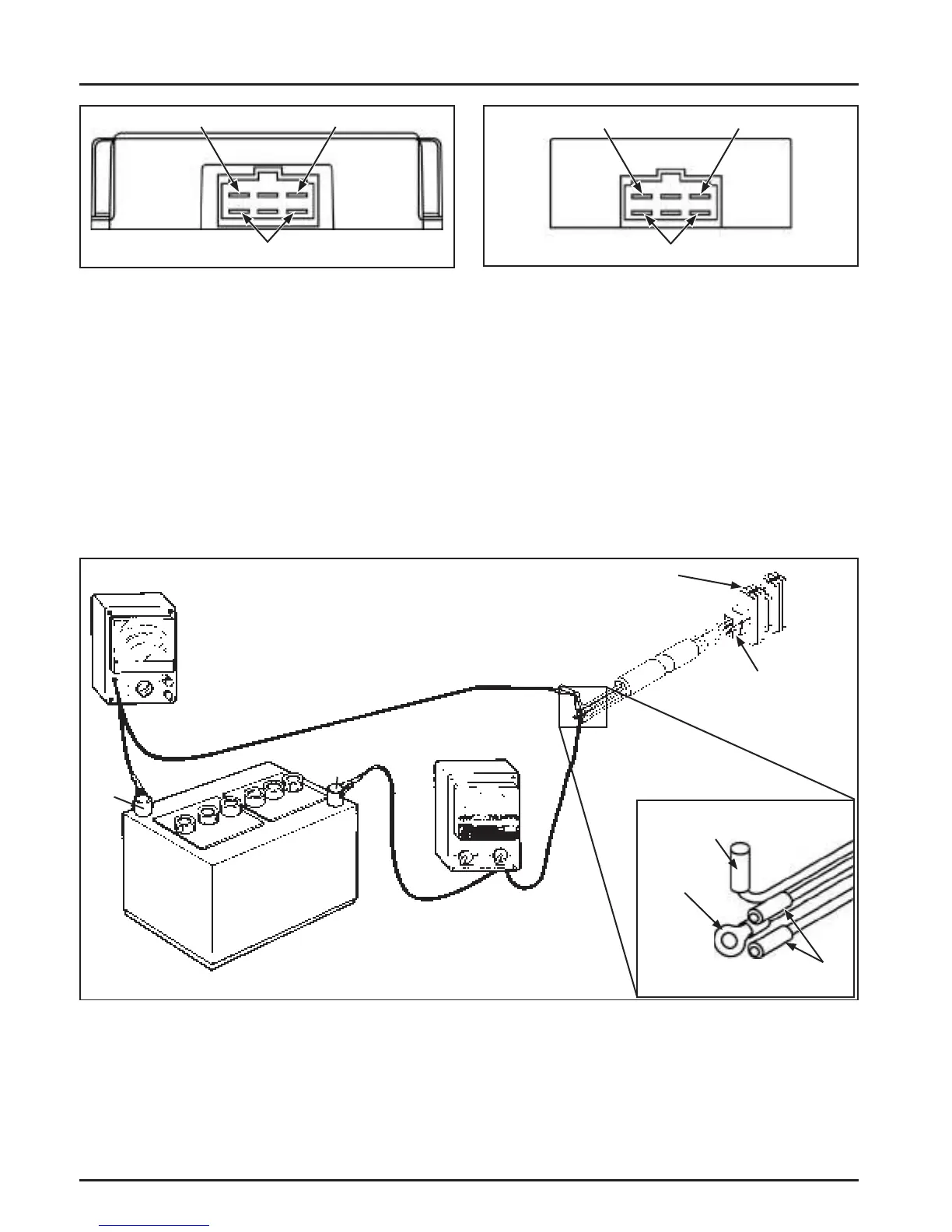
Stator Leads
B+ Charge (White) Ground (Black)
Figure 8-8. 18 Amp Rectifi er-Regulator.
Stator Leads
B+ Charge (White) Ground (Black)
Figure 8-9. 10 Amp Rectifi er-Regulator.
Connect Tester Leads to
Female Bullet Connector
Ground
Lead
Stator AC Leads
(+)
(-)
Rectifi er-Regulator
Plug in
Connector
Rectifi ed Only (Non-Regulated) Systems
Some engines are equipped with a rectifi ed only, non-regulated charging system, with output ranging from 3
amps to 4 amps. The rectifi er is normally connected to the engine with a matching wiring harness and secured
inside the control panel. Grounding is achieved through the wiring harness. The rectifi er converts AC voltage
coming from the stator to DC voltage only.
Troubleshooting Guide
Battery Charging System
NOTE: Zero ohmmeters on each scale to ensure accurate readings. Voltage tests should be made with engine
running at 3600 RPM - no load. Ba ery must be fully charged. Check the specifi c gravity of ba ery. If
low, recharge or replace ba ery as necessary.
Figure 8-10. Connections for Testing Charging Systems.
 Loading...


