11.20
Section 11
Reassembly
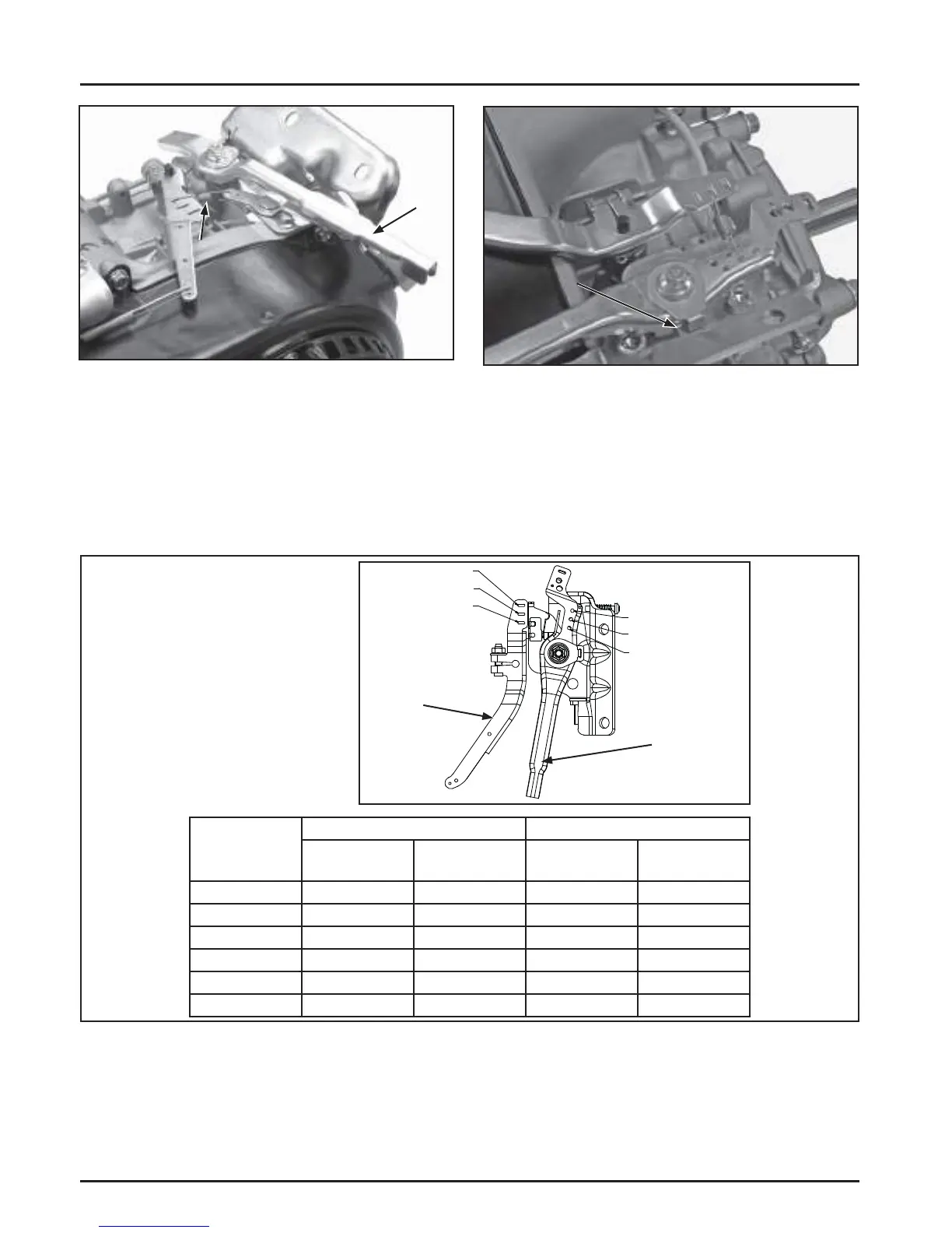
Engine Speed
RPM
8-12% Droop 5-8% Droop
Spring Color
Hole
Combination
Spring Color
Hole
Combination
3801-4000 Red #3-A
3601-3800 Red #3-A Yellow #2-A
3401-3600 Red #2-A
3201-3400 Yellow #2-A
3001-3200 Yellow #1-A Black #1-B
2801-3001 Yellow #1-B
A
B
C
3
2
1
Governor
Lever
Throttle
Control
Lever
Governor Lever and Hole Position/RPM Chart
CH270 Engines
Washer Tab
In Slot
Figure 11-78. Install Throttle Lever for CH395,
CH440.
5. Install a nylon washer, wave spring, and tabbed
washer (with tab engaged in slot) on the stud
above the thro le lever and secure with a hex
fl ange nut. Torque the hex fl ange nut to 9 N·m (80
in. lb.). See Figure 11-79.
Figure 11-79. Throttle Lever Hardware.
Throttle
Lever
Spring
 Loading...


