11.17
Section 11
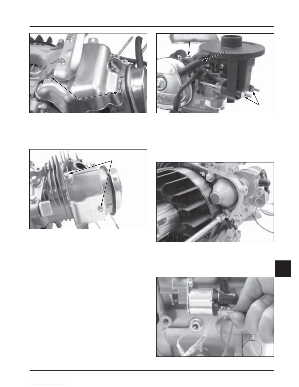
Reassembly
11
Figure 11-64. Install Upper Heat Shield.
2. Install lower shield on the cylinder and secure
with two hex fl ange screws. Torque to 8 N·m
(71 in. lb.). See Figure 11-65.
Figure 11-65. Install Lower Heat Shield.
3. Install a new carburetor to air cleaner base gasket
onto the carburetor mounting studs followed by
the air cleaner base. A ach the breather hose onto
the air cleaner base connection port. Connect the
opposite end of the breather hose to the valve
cover. See Figure 11-66.
4. Secure the base with the two hex fl ange nuts on
the mounting studs and one hex fl ange screw into
the crankcase housing. Torque hardware to 8 N·m
(71 in. lb.). See Figure 11-66.
NOTE: When securing the low-profi le air cleaner, the
hex fl ange screw is installed through the base
into the blower housing. Torque to 6.7 N·m
(59 in. lb.).
Hex Screws
Figure 11-66. Air Cleaner Base Installation.
Install Electric Starter and Control Panel
(If Equipped)
1. Align and mount the electric starter onto the
crankcase. Install and torque the two hex fl ange
screws to 24 N·m (212 in. lb.). See Figure 11-67.
Breather
Hose
Hex Screw
Hex Nuts
Hex Screws
Figure 11-67. Align and Mount Starter.
2. Connect the electrical leads for the Oil Sentry™,
ignition module, key switch, relay, and starter.
See Figure 11-68.
Figure 11-68. Connect Electrical Leads.
 Loading...


