9.7
Section 9
Disassembly
9
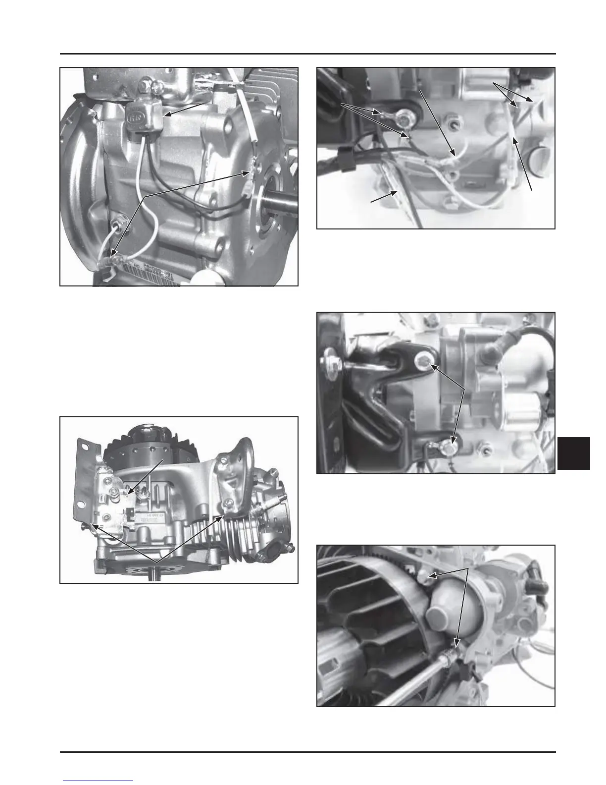
Figure 9-27. Disconnect Wires from Control Panel.
2. Remove the hex fl ange screws securing the
control panel bracket to the crankcase, and
remove the control panel. Note the two ground
wires secured by one of the screws.
Control Panel
Screws
Figure 9-28. Remove Control Panel Screws.
3. Remove the hex fl ange screws securing the
electric starter to the crankcase, and remove the
electric starter.
Electric Starter
Screws
Figure 9-29. Remove Electric Starter Screws.
Module
Bullet
Connectors
Figure 9-25. Disconnect Oil Sentry™ System.
2. Remove both fuel tank brackets by removing
the two screws in each. Remove the threaded
stud from the le bracket and remove the micro
switch bracket. See Figure 9-26.
NOTE: For CH395 and CH440 it is not required and
not recommended to remove the threaded
stud and micro switch bracket.
Fuel Tank Brackets
Micro Switch
Bracket
Figure 9-26. Fuel Tank Bracket Removal.
Remove Control Panel and Electric Starter
(If Equipped)
1. Disconnect the wires from the control panel to
the starter, Oil Sentry™, ignition module, and the
rectifi er-regulator. See Figure 9-27.
NOTE: To ease reassembly, label wires for proper
reconnection as wiring colors may not match.
Starter
Wires
Rectifi er-
Regulator
Wire
Ground
Wires
Ignition
Module
Wire
Oil Sentry
™
Wire
 Loading...


