10.12
Section 10
Inspection and Reconditioning
Figure 10-16. Piston Ring Expander.
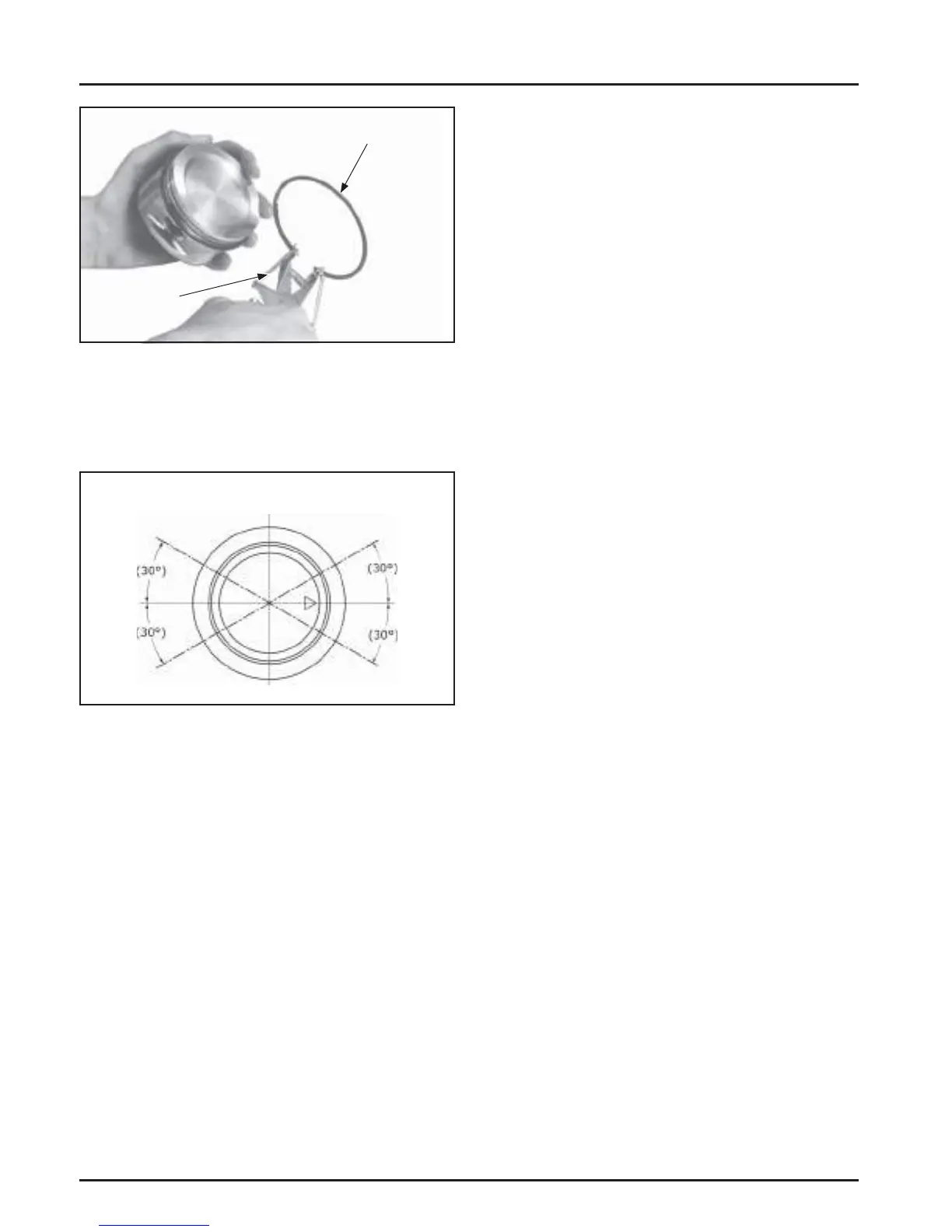
1. Oil Control Ring (Bo om Groove): Install the
expander and then the rails. Make sure the ends
of the expander are not overlapped. See Figure
10-17.
Oil Ring
Expander Gap
Top Ring
Gap
2nd Ring
Gap
Bottom Oil
Rail Gap
Top Oil
Rail Gap
Figure 10-17. Piston Ring Orientation.
2. Middle Compression Ring (Center Groove):
Install the center ring using a piston ring
expander tool. Make sure the identifi cation mark
is up or the colored dye stripe (if contained) is to
the le of the end gap. See Figure 10-17.
3. Top Compression Ring (Top Groove): Install the
top ring using a piston ring expander tool. Make
sure the identifi cation mark is up or the colored
dye stripe (if contained) is to the le of the end
gap. See Figure 10-17.
Connecting Rods
Off set, stepped-cap connecting rods are used in all
these engines.
Inspection and Service
Check the bearing area (big end) for excessive wear,
score marks, running and side clearances (see Section
1, Specifi cations and Tolerances). Replace the rod and
cap if scored or excessively worn.
Piston Ring
Piston Ring
Expander
Service replacement connecting rods are available
in STD size and 0.25 mm (0.010 in.) undersize.
The 0.25 mm (0.010 in.) undersized rods have an
identifi cation marking on the lower end of the
rod shank. Always refer to the appropriate parts
information to ensure that correct replacements are
used.
Closure Plate Assembly
Inspection
Inspect the main bearing surface for wear or damage.
Refer to Section 1, Specifi cations and Tolerances.
Replace the closure plate if required.
Governor Assembly (Internal)
Inspection
Inspect the governor gear teeth. Replace the gear if it
is worn, chipped, or if any teeth are missing. Inspect
the governor weights. They should move freely in the
governor gear.
Breather Design
The breather system is designed to control the amount
of oil in the head area and still maintain the necessary
vacuum in the crankcase. The system includes an
inner chamber in the valve cover containing a mesh
fi lter, spring steel reed, and retainer.
When the pistons move downward, crankcase gases
move through a passage to the inner chamber. In
turn, air is pushed past the reed to the intake system.
The upward travel of the pistons closes the reed and
creates a low vacuum in the lower crankcase. This
separates the oil from the airfl ow in the mesh fi lter.
Any oil separated through the fi lter drains back into
the crankcase through a small hole in the inner valve
cover.
 Loading...


