8.7
Section 8
Electrical System and Components
8
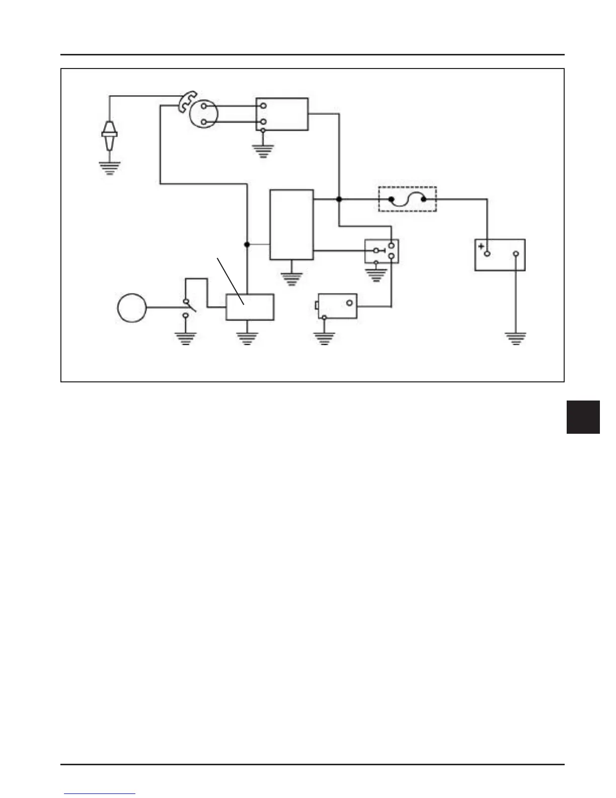
Figure 8-7. Wiring Diagram-10/18 Amp Charging System, With Rectifi er-Regulator.
NOTE: Observe the following guidelines to
avoid damage to the electrical system and
components.
• Make sure the ba ery polarity is correct. A
negative (-) ground system is used.
• Make sure all ground connections are secure
and in good condition.
• Disconnect both ba ery cables before doing
electrical welding on the equipment powered
by the engine. Also, disconnect other electrical
accessories in common ground with the engine.
• Prevent the stator (AC) leads from touching or
shorting while the engine is running. This can
damage the stator.
Stator
The stator is mounted on the crankcase behind the
fl ywheel. Should the stator have to be replaced, follow
the procedures in Section 9 Disassembly.
Rectifi er-Regulator
The rectifi er-regulator is connected to the engine
with a matching wiring harness containing a plug-in
connector. Grounded through the wiring harness,
the rectifi er-regulator is secured to the equipment
in a suitable location with two mounting screws. To
replace it, disconnect the plug, and remove the two
mounting screws.
NOTE: When installing the rectifi er-regulator, push
the wiring harness plug into the regulator
receptacle until it locks into place.
The rectifi er-regulator converts the AC voltage coming
from the stator to DC voltage, while also monitoring
and controlling the ba ery voltage. There are two
diff erent rectifi er-regulators which are used; an 18
amp and a 10 amp assembly. Although externally
similar, the internal circuits diff er and the two should
not be interchanged. See Figures 8-8 and 8-9.
Ignition
Module
Spark
Plug
Oil Float
Switch
Oil Control
Module
Key
Switch
Battery
Fuse
Relay
Starter
Motor
12 Volt
Battery
Rectifi er-
Regulator
Stator
 Loading...


