5.9
Section 5
Fuel System and Governor
5
Speed Increasing Speed Decreasing
13. Hold the carburetor body so the fl oat assembly
hangs vertically and rests lightly against the
fuel inlet needle. The inlet needle should be
fully seated but the center pin of the needle (on
retainer clip end) should not be depressed.
NOTE: The inlet needle center pin is spring
loaded. Make sure the fl oat assembly
rests against the fuel inlet needle,
without depressing the center pin.
14. Install the fuel bowl, with the O-ring(s) in
place, onto the carburetor. Secure with O-ring
on original screw. Torque the screw to 7.0 N·m
(62 in. lb.).
Carburetor Installation
Always use new gaskets when servicing or reinstalling
carburetors. Repair kits are available which include
new gaskets and other components. Service kit part
numbers can be found in our free online parts lookup
Kohler PLUS. Go to www.kohlerplus.com and click
Enter as a Guest.
1. Reverse the steps in Carburetor Removal to
install the carburetor to the engine.
Governor
These engines are equipped with a centrifugal
fl yweight mechanical governor. The governor is
designed to hold the engine speed constant under
changing load conditions. The governor gear/
fl yweight mechanism is mounted inside the crankcase
and driven off the gear on the cranksha .
Operation
Centrifugal force acting on the rotating governor gear
assembly causes the fl yweights to move outward as
speed increases. As the fl yweights move outward,
they cause the regulating pin to extend from the
governor gear assembly. See Figure 5-17.
Figure 5-17. Action of a Governor Gear.
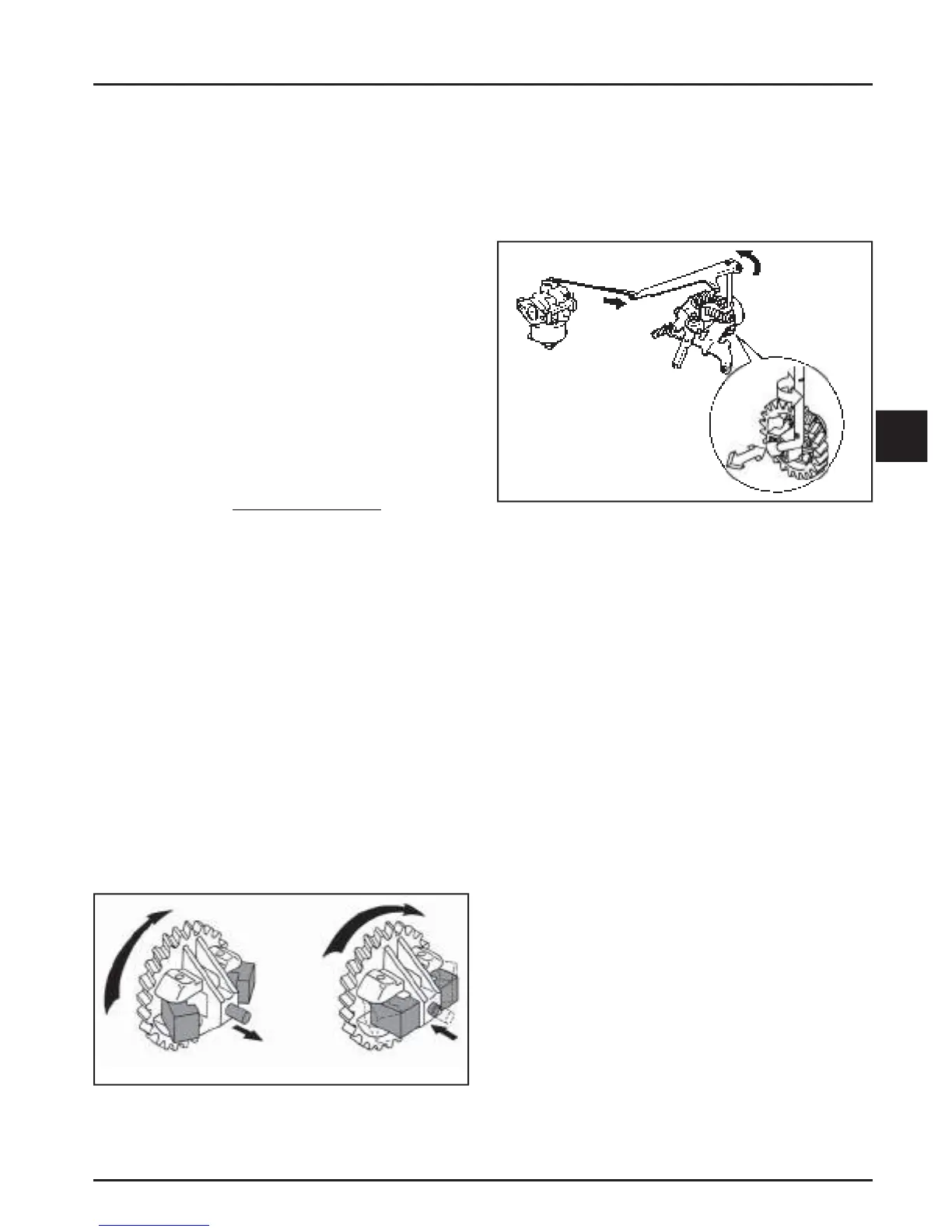
The regulating pin contacts the tab on the cross sha ,
causing the sha to rotate when the engine speed
changes. One end of the cross sha protrudes through
the side of the closure plate. Through external linkage
a ached to the cross sha , the rotating action is
transmi ed to the thro le lever of the carburetor. See
Figure 5-18.
Figure 5-18. Typical Governor System.
When the engine is at rest, and the thro le control
is in the FAST position, the tension of the governor
spring holds the thro le plate open. When the engine
is operating (the governor gear assembly is rotating),
the force applied by the regulating pin against the
cross sha tends to close the thro le plate. The
governor spring tension and the force applied by the
regulating pin are in equilibrium during operation,
holding the engine speed constant.
When a load is applied and the engine speed (and
governor gear speed) decreases, the governor spring
tension moves the governor lever to open the thro le
plate wider. This allows more fuel into the engine,
increasing engine speed (this action occurs very
rapidly, so a reduction in speed is hardly noticed). As
the speed reaches the governed se ing, the governor
spring tension and the force applied by the regulating
pin will again be in equilibrium. This maintains the
engine speed at a relatively constant level.
The governed speed se ing is determined by the
position of the thro le control. It can be variable or
constant, depending on the application.
 Loading...


