11.6
Section 11
Reassembly
Throttle Lever
Dipper
Orientation
Piston
Index Mark
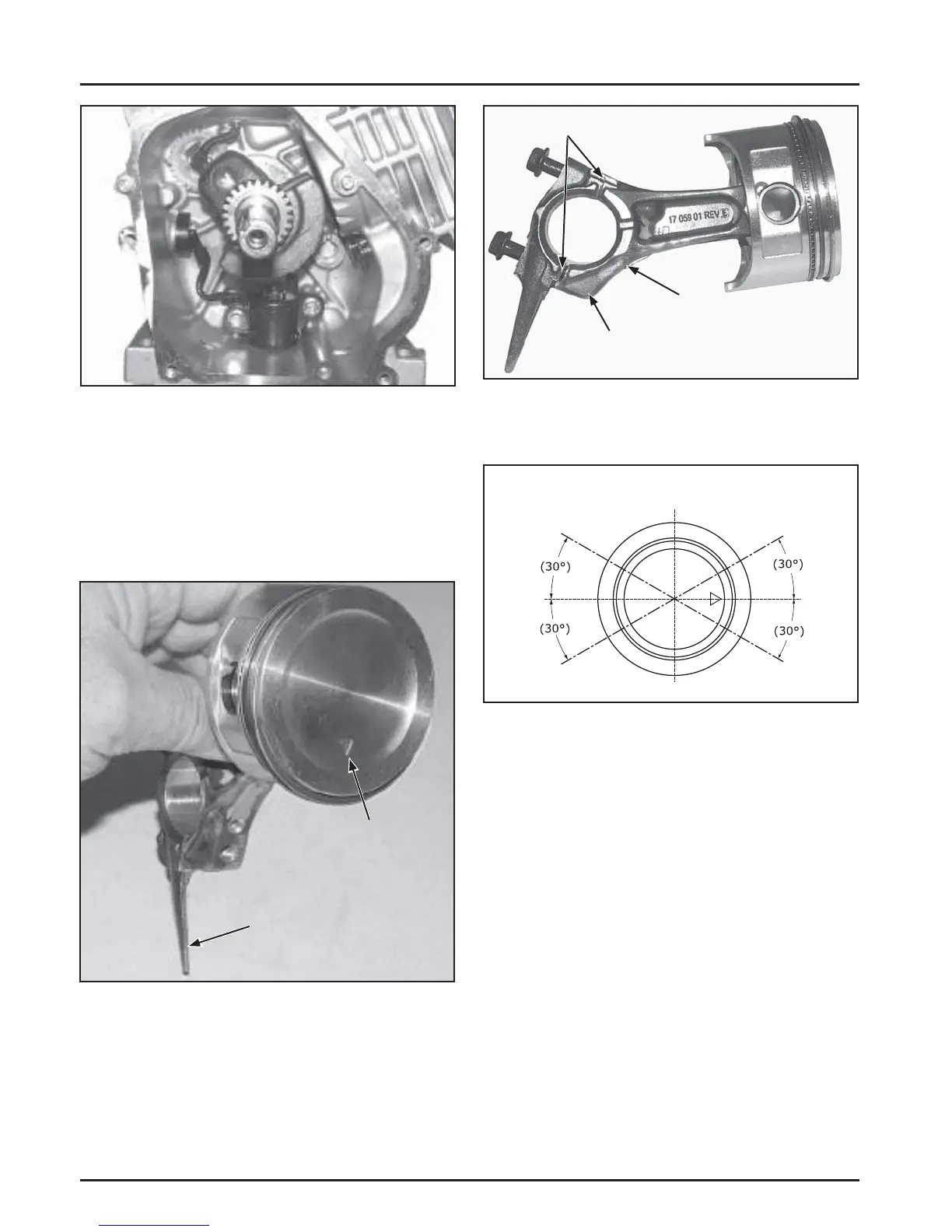
Figure 11-21. Piston/Connecting Rod Orientation.
b. The connecting rod off set is down and oil
hole is in the 4 o’clock position shown. Match
marks should align as shown with dipper
down. See Figure 11-22.
Figure 11-20. Installing Crankshaft.
Install Connecting Rod with Piston and
Rings
1. Make sure the following is correct before
installing.
a. The locating mark on the piston is down. See
Figure 11-21.
Connecting
Rod Offset
Match Marks
Oil Hole
Location
Figure 11-22. Connecting Rod Details.
2. Stagger the piston rings in the grooves as shown
in Figure 11-23.
Oil Ring
Expander Gap
Top
Ring
Gap
2nd Ring
Gap
Bottom Oil
Rail Gap
Top Oil
Rail Gap
Figure 11-23. Piston Ring Orientation.
3. Lubricate cylinder bore, piston, piston pin, and
piston rings with engine oil. Compress the rings
using a piston ring compressor.
4. Lubricate the cranksha journal and connecting
rod bearing surfaces with engine oil.
5. Ensure ‘‘’’ stamping on piston is facing down
toward the base of the engine. Use a hammer
handle or rounded wood dowel and gently
tap the piston into the cylinder as shown in
Figure 11-24. Be careful that the oil ring rails do
not spring free between the bo om of the ring
compressor and the top of the cylinder.
 Loading...


