WaveSurfer DSO
WS-OM-E Rev B 111
6. The FFT Power Average takes the complex frequency-domain data R'
n
and I'
n
for each
spectrum generated in Step 5, and computes the square of the magnitude:
M
n
2
= R'
n
2
+ I'
n
2
,
then sums M
n
2 and counts the accumulated spectra. The total is normalized by the
number of spectra and converted to the selected result type using the same formulas as
are used for the Fourier Transform.
Glossary
This section defines the terms frequently used in FFT spectrum analysis and relates them to the
oscilloscope.
Aliasing If the input signal to a sampling acquisition system contains components whose
frequency is greater than the Nyquist frequency (half the sampling frequency), there will be less
than two samples per signal period. The result is that the contribution of these components to the
sampled waveform is indistinguishable from that of components below the Nyquist frequency.
This is aliasing.
The timebase and transform size should be selected so that the resulting Nyquist frequency is
higher than the highest significant component in the time-domain record.
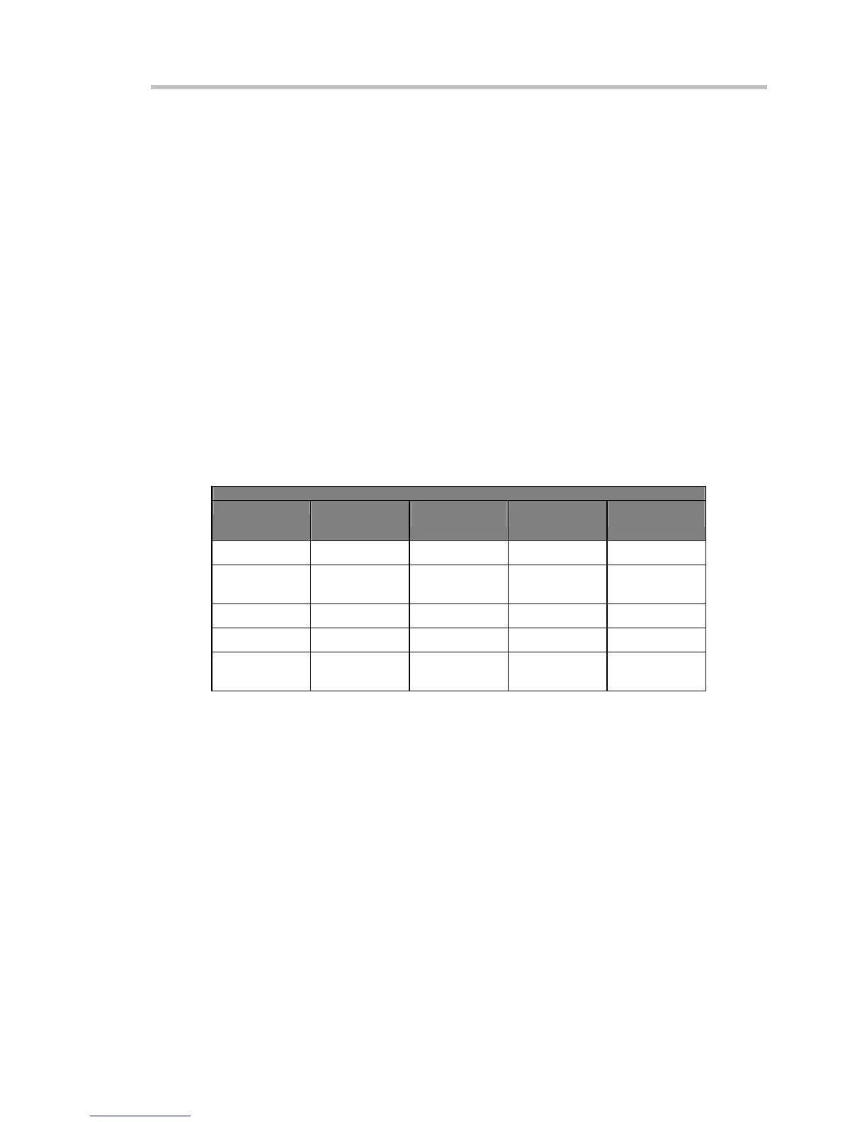
Coherent Gain The normalized coherent gain of a filter corresponding to each window function is
1.0 (0 dB) for a rectangular window and less than 1.0 for other windows. It defines the loss of
signal energy due to the multiplication by the window function. This loss is compensated for in the
oscilloscope. The following table lists the values for the implemented windows.
Window Frequency Domain Parameters
Window Type Highest Side
Lobe
(dB)
Scallop Loss
(dB)
ENBW
(bins)
Coherent Gain
(dB)
Rectangular
–13 3.92 1.0 0.0
Hanning (Von
Hann)
–32 1.42 1.5 – 6.02
Hamming
–43 1.78 1.37 –5.35
Flattop
–44 0.01 2.96 –11.05
Blackman–
Harris
–67 1.13 1.71 –7.53
ENBW Equivalent Noise BandWidth (ENBW) is the bandwidth of a rectangular filter (same gain at
the center frequency), equivalent to a filter associated with each frequency bin, which would
collect the same power from a white noise signal. In the table on the previous page, the ENBW is
listed for each window function implemented, given in bins.
Filters Computing an N-point FFT is equivalent to passing the time-domain input signal through
N/2 filters and plotting their outputs against the frequency. The spacing of filters is Delta f = 1/T,
while the bandwidth depends on the window function used (see Frequency Bins).

 Loading...