EasyManua.ls Logo

LeCroy WAVESURFER User Manual

LeCroy WAVESURFER
128 pages
To Next Page IconTo Next Page
To Previous Page IconTo Previous Page
Page #70 background imageLoading...
Page #70 background image
WaveSurfer DSO
WS-OM-E Rev B 65
5. Select Positive or Negative slope.
6. Touch inside the Level field and enter a voltage value.
7. Touch inside the Trigger after timeout data entry field and enter a time window using the
pop-up numeric keypad.
Logic Trigger
How Logic Trigger Works
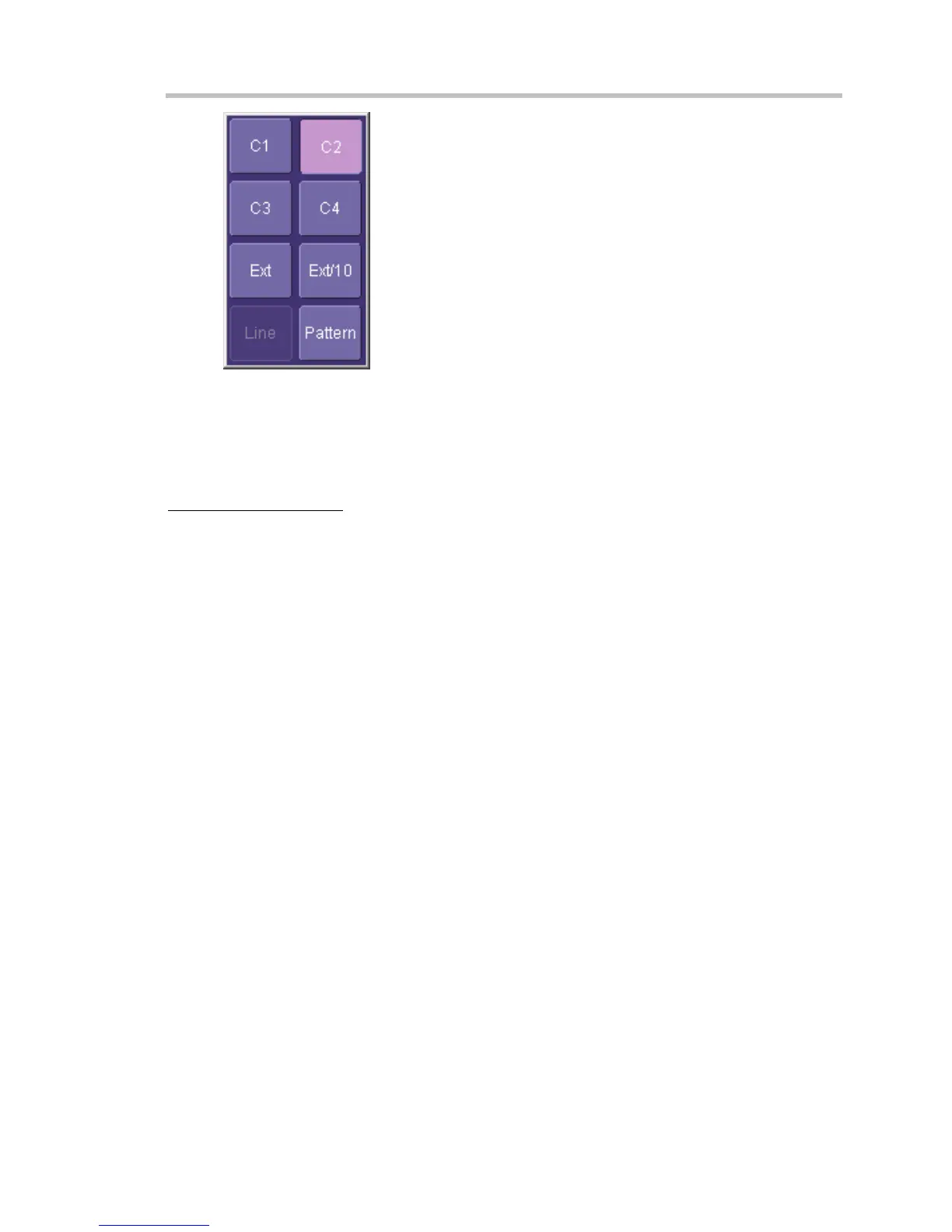
Logic Trigger enables triggering on a logical combination of up to five inputs: CH 1, CH 2, CH 3,
CH 4, and EXT. The combination of inputs is referred to as a pattern. There are four logic gates
available: AND, NAND, OR, NOR.
A trigger state is either high or low: high when a trigger source is greater than the trigger level
(threshold) and low when less than it. For example, an AND pattern could be defined as true
when the trigger state for CH 1 is high, CH 2 is low, and EXT is irrelevant (X or don't care). If any
one of these conditions is not met, the pattern state is considered false. You can set holdoff limits
from 2 ns to 20 s or from 1 to 1,000,000,000 events.

Table of Contents

Question and Answer IconNeed help?

Do you have a question about the LeCroy WAVESURFER and is the answer not in the manual?

LeCroy WAVESURFER Specifications

General IconGeneral
Input CouplingAC, DC, GND
InterfaceUSB, LAN, GPIB (optional)
Channels4
Display10.4" LCD
Vertical Resolution8 bits
Input Impedance1 MΩ || 50 Ω
Max Input Voltage400 Vpk (1 MΩ)
Trigger ModesEdge, Pattern
Bandwidth200 MHz to 1 GHz

Summary

HOW TO USE ON-LINE HELP

Instrument Help

Accessing help specific to instrument controls and features via dedicated buttons or menus.

Windows Help

Accessing help for the underlying Windows operating system features by minimizing the scope application.

WARRANTY

Warranty and Service

Details warranty terms, conditions, and service procedures.

SPECIFICATIONS

Vertical System

Specifications for vertical signal acquisition.

Horizontal System

Specifications for horizontal timebase.

Triggering System

Specifications for trigger functionality.

INSTALLATION

Hardware Installation

Instructions for physical setup and connections.

CONNECTING TO A SIGNAL

ProBus Interface

Details the ProBus probe connection system.

SAMPLING MODES

Single-shot sampling mode

Explanation of single-shot acquisition.

VERTICAL SETTINGS AND CHANNEL CONTROLS

Adjusting Sensitivity and Position

How to adjust vertical gain and offset.

Coupling

Options for signal coupling (AC, DC, GND).

TIMEBASE AND ACQUISITION SYSTEM

Timebase Setup and Control

How to configure timebase settings.

TRIGGERING

Simple Triggers

Covers basic edge triggering.

SMART Triggers

Details advanced trigger types like Glitch and Width.

DISPLAY FORMATS

Display Setup

Configuring grid, intensity, and line styles.

Persistence Setup

Using persistence to view waveform history.

SAVE AND RECALL

Saving and Recalling Scope Settings

Procedures for saving/loading instrument setups.

PRINTING AND FILE MANAGEMENT

Printing

Setting up and performing print operations.

WAVEFORM MEASUREMENTS

Measuring with Cursors

Using cursors for precise measurements.

Parameter Calculations

Explains various waveform parameters and their calculation.

WAVEFORM MATH

Introduction to Math Traces and Functions

Overview of applying mathematical operations to waveforms.

FFT

Details the Fast Fourier Transform analysis.

UTILITIES

Status

Accessing system status and configuration.

Remote communication

Setting up network communication for remote control.

Options

Preferences

Customizing instrument behavior and settings.

Related product manuals