RFI lters / Mains lters
RFI and mains lters are used to ensure compliance with the EMC requirements of European
Standard EN 61800-3. This standard denes the EMC requirements for electrical drive system
in various categories.
•
RFI lters are capacive accessory components. RFI lters reduce conducted noise emis-
sions. RFI lters are also called EMC lters.
•
Mains lters are a combinaon of mains choke and RFI lter. Mains lters reduce the con-
ducted noise emission.
Denion of the environments
(EN 61800−3)
First environment
The rst environment comprises residenal buildings or locaons that are directly connected
to a low-voltage system for supplying residenal areas.
Second environment
The second environment comprises facilies or locaons that are not directly connected to a
low-voltage system for supplying residenal areas.
Category C1
Category C1 denes the requirements for drive systems that are intended for the use in the
rst environment at a rated voltage lower than 1000 V.
The limit values of the EN 61800−3 comply with EN 55011 class B.
Category C2
Category C2 denes the requirements for permanently installed drive systems that are inten-
ded for the use in the rst environment at a rated voltage lower than 1000 V. Installaon and
commissioning must only be carried out by qualied personnel with EMC knowledge.
The limit values of the EN 61800−3 comply with EN 55011 class A group 1.
Category C3
Category C3 denes the requirements for drive systems that are exclusively intended for the
use in the second environment at a rated voltage lower than 1000 V.
The limit values of the EN 61800−3 comply with EN 55011 class A group 2.
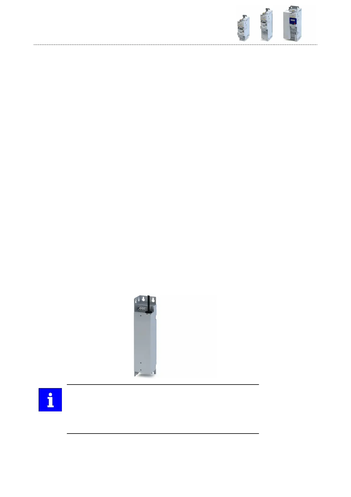
When working with stricter line-bound noise emission requirements which can-
not be met using the radio interference suppression measures integrated in the
inverter, external lters can be used. The lters can be installed below or next to
the inverter.
If necessary, the internal lters have to be deacvated when external lters are
used. For this purpose, remove the IT screws of the inverters.
Accessories
RFI lters / Mains lters
246

 Loading...


