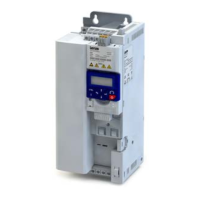
Handling
Transport, storage
Observe the notes regarding transport, storage and correct handling. Ensure proper handling
and avoid mechanical stress. Do not bend any components and do not change any insulaon
distances during transport or handling. Do not touch any electronic components and contacts.
Inverters contain electrostacally sensive components which can easily be damaged by inap-
propriate handling. Do not damage or destroy any electrical components since thereby your
health could be endangered!
Installaon
The technical data and supply condions can be obtained from the nameplate and the docu-
mentaon. They must be strictly observed.
The inverters have to be installed and cooled according to the regulaons given in the corre-
sponding documentaon Observe the climac condions according to the technical data. The
ambient air must not exceed the degree of polluon 2 according to EN 61800−5−1.
Electrical connecon
When working on live inverters, observe the applicable naonal regulaons for the prevenon
of accidents.
The electrical installaon must be carried out according to the appropriate regulaons (e. g.
cable cross-secons, fuses, PE connecon). Addional informaon can be obtained from the
documentaon.
This documentaon contains informaon on installaon in compliance with EMC (shielding,
earthing, lter, and cables). These notes must also be observed for CE-marked inverters. The
manufacturer of the system is responsible for compliance with the limit values demanded by
EMC legislaon. The inverters must be installed in housings (e. g. control cabinets) to meet the
limit values for radio interferences valid at the site of installaon. The housings must enable
an EMC-compliant installaon. Observe in parcular that e. g. the control cabinet doors have
a circumferenal metal connecon to the housing. Reduce housing openings and cutouts to a
minimum.
Inverters may cause a DC current in the PE conductor. If a residual current device (RCD) is used
for protecon against direct or indirect contact for an inverter with three-phase supply, only a
residual current device (RCD) of type B is permissible on the supply side of the inverter. If the
inverter has a single-phase supply, a residual current device (RCD) of type A is also permissi-
ble. Apart from using a residual current device (RCD), other protecve measures can be taken
as well, e. g. electrical isolaon by double or reinforced insulaon or isolaon from the supply
system by means of a transformer.
operaon
If necessary, systems including inverters must be equipped with addional monitoring and
protecon devices. Also comply with the safety regulaons and provisions valid at the installa-
on site.
Aer the inverter has been disconnected from the supply voltage, all live components and
power terminals must not be touched immediately because capacitors can sll be charged.
Please observe the corresponding sckers on the inverter.
All protecon covers and doors must be shut during operaon.
You may adapt the inverters to your applicaon by parameter seng within the limits availa-
ble. For this, observe the notes in the documentaon.
Safety funcons
Certain inverter versions support safety funcons (e. g. ”safe torque o”, formerly ”safe stand-
sll”) according to the requirements of the EC Machinery Direcve 2006/42/EC. The notes on
the integrated safety provided in this documentaon must be observed.
Maintenance and servicing
The inverters do not require any maintenance if the prescribed operang condions are
observed.
Informaon on project planning
Safety instrucons
Handling
35

 Loading...


