GENERAL INFORMATION
90-883728 JULY 2001 Page 1C-9
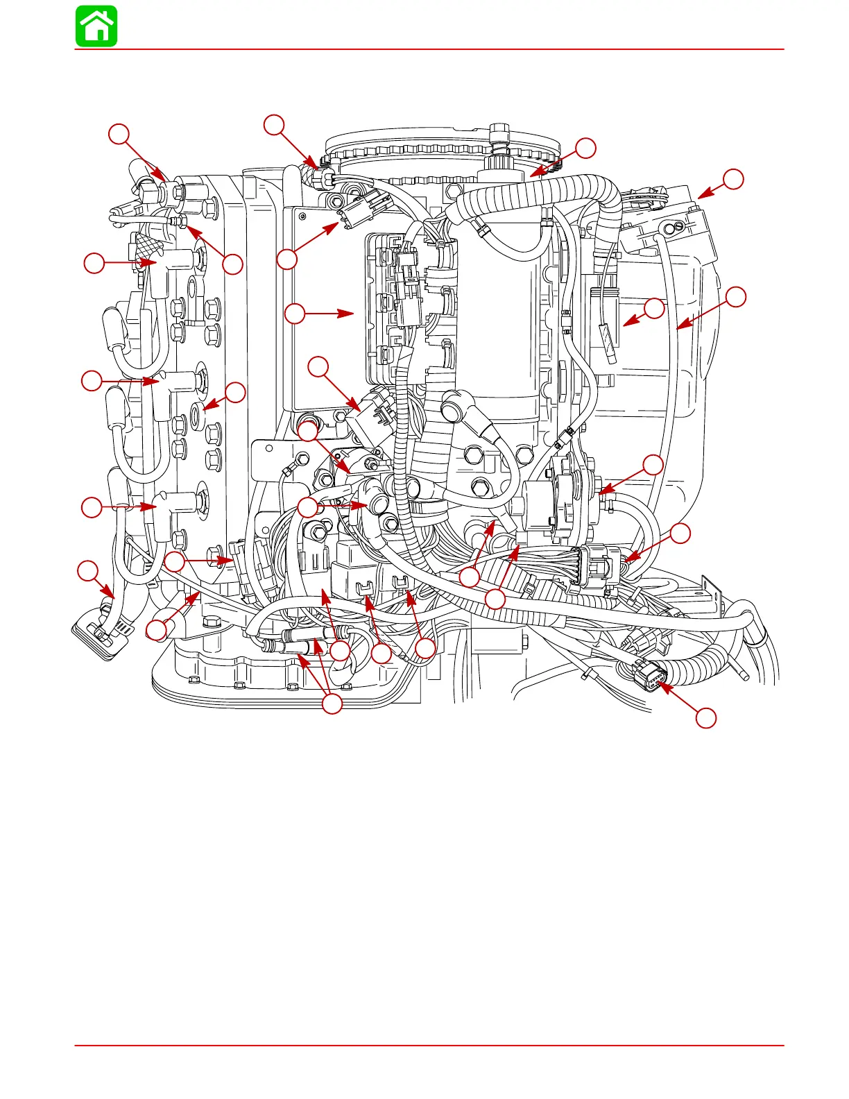
Model 150 XRI/175 XRI/200 XRI Powerhead Starboard View
58778
1
2
3
4
5
6
7
8
9
10
11
12
13
14
15
16
17
18
19
20
21
22
23
24
25
26
27
28
1-Starter Motor
2-Throttle Plate Assembly
3-Fuel Regulator Vacuum Hose
4-Engine Harness Connector
5-Oil Pump
6-Fuel Injector Harness Connector
7-Cowl Trim Connector
8-Oil Pump Harness Connector
9-Negative Battery Cable
10 - Trim DOWN Relay
11 - Trim UP Relay
12 - Main Power Relay
13 - Trim Motor Bullet Connectors
14 - Positive Battery Cable
15 - Starter Solenoid
16 - 20 Ampere Fuses (3); 15 Ampere Fuse (1)
17 - Electronic Control Module (ECM)
18 - Digital Diagnostic Connector
19 - Temperature Sensor (Engine Overheat)
20 - Detonation Sensor (200 EFI Only)
21 - Detonation Sensor Connector (200 EFI Only)
22 - Water Pressure Gauge Hose
23 - Tell-Tale Hose
24 - #5 Cylinder
25 - #3 Cylinder
26 - #1 Cylinder
27 - Starboard Thermostat [143°F (61.7°C)]
28 - Crank Position Sensor Connector
 Loading...


