POWER TRIM
90-883728 JULY 2001 Page 5B-17
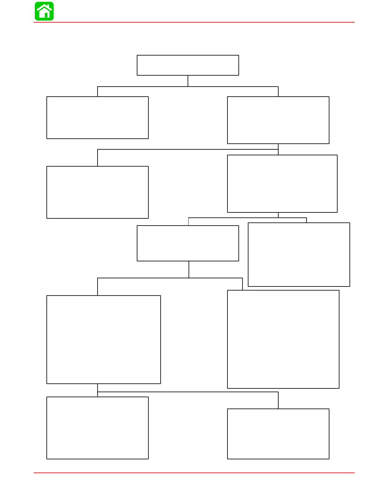
Troubleshooting the “Down” and “Up” Circuits
(All Circuits Inoperative)
Battery Voltage Indicated:
No Voltage Indicated:
Battery Voltage Indicated:
Battery Voltage Indicated:
Battery Voltage Indicated:
No Voltage Indicated:
No Voltage Indicated:
No Voltage Indicated:
Blown Fuse:
Fuse Not Blown:
Check in-line fuse (under cowl)
to see if fuse is blown.
•Correct problem that caused
fuse to blow.
•Replace fuse.
•Check battery leads for poor
connections or open circuits.
•Check battery charge.
•Connect Voltmeter red lead to
Point 8 and black lead to
ground.
•Depress “Up” trim button and
check for battery voltage.
•Check black ground wires for
poor connection or poor
ground, Point 10.
•Pump motor is faulty. Refer to
“Motor and Electrical Tests/
Repair”, following.
•Check for open in wire.
•Check for loose or corroded
connections.
•Check for voltage at any instru-
ment, using a Voltmeter.
•Turn ignition switch to “Run”
position.
•DO NOT start engine.
•Check for pinched or severed
wires.
•Check all trim harness con-
nectors for loose or corroded
connections.
•Check trim switch.
Connect Voltmeter red lead to
Point 3 and black lead to
ground. Battery voltage should
be indicated.
There is an open circuit in wire
between Point 5 and Red ter-
minal on the back of the ignition
switch.
Red wire is open between Point
3 and red terminal on back of
the ignition switch.
Check that voltage is being
supplied to control by performing
the following checks:
Connect red Voltmeter lead to
Point 5, and black lead to
ground.
Trim switch is faulty or there is an
open circuit in wires (green-white,
blue-white) between trim buttons
and trim pump.
 Loading...


