POWERHEAD
90-883728 JULY 2001 Page 4A-17
CYLINDER HEAD BOLTS
Apply light oil to threads and bolt face: 30 lb. ft. (40.7 N·m) and rotate 90°
10
6
2
3
7
11
12
8
4
1
5
9
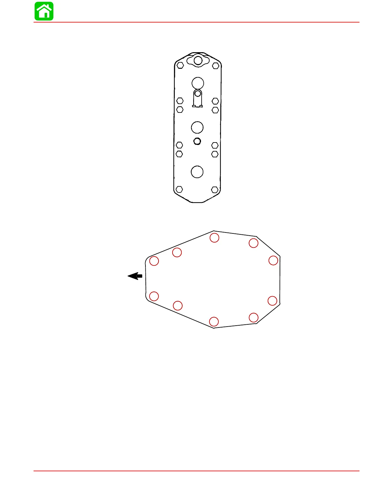
POWERHEAD TO ADAPTOR PLATE ATTACHING NUT
Torque nuts to 25 lb. ft. (33.8 Nm)
Port Side
Starboard Side
1
2
3
4
5
6
7
8
9
10
Front
General Information
Powerhead “Disassembly” and “Reassembly” instructions are printed in a sequence that
should be followed to assure best results when removing or replacing powerhead compo-
nents. If complete disassembly is not necessary, start reassembly at point disassembly was
stopped. (Refer to “Table of Contents,” preceding.) Usually, complete disassembly of pow-
erhead will be required.
If major powerhead repairs are to be performed, remove powerhead from drive shaft hous-
ing. Removal of powerhead is not required for 1) inspection of cylinder walls and pistons
(refer to “Powerhead Removal and Disassembly,” following, and remove cylinder heads and
exhaust cover), 2) minor repairs on components, such as ignition system, carburetors, reed
blocks and cylinder heads and checking operation of thermostats.
 Loading...


