POWER TRIM
90-883728 JULY 2001 Page 5B-29
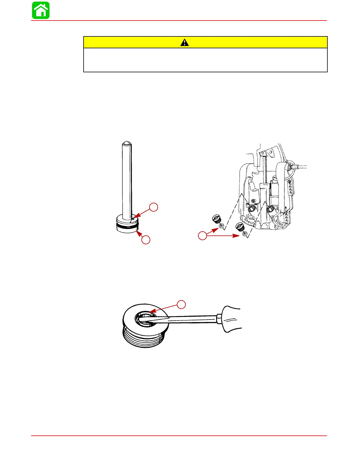
CLEANING AND INSPECTION - TRIM RODS AND CAPS
CAUTION
Do not remove check valve (a). Check valve is preset to operate at a specific pres-
sure. Removal and installation of check valve could result in improper operating
pressure and possible system damage.
NOTE: Check valve is in port side trim rod only.
NOTE: Certain models may have trim limit reducers installed on the trim rod to limit trim
out angle. Each reducer limits the amount of total trim by 2
°.
A maximum of 5 reducers
may be installed on each trim rod.
1. Inspect check valve and check valve screen for debris; if debris cannot be removed,
replace trim rod assembly. Clean trim rod with parts cleaner and dry with compressed
air.
51352
a
b
a
b
57886
c
a-Check Valve
b-Check Valve Screen
c-Trim Limit Reducers
Trim Rod End Cap Seal
1. Inspect trim cap end seal and replace if damaged or if seal does not keep trim rod
clean.
51343
a
a
a-Seal (remove as shown)
2. Install new seal with seal lip up.
TRIM ROD INSTALLATION
IMPORTANT: Components must be free of dirt and lint. Any debris in the system
can cause system to malfunction.
NOTE: Install trim rod with check valve in the port (left) cylinder.
1. Apply Quicksilver Power Trim and Steering Fluid on all O-rings and seals before in-
stallation.
 Loading...


