7Appendix
Spline interpolation Appendix-625
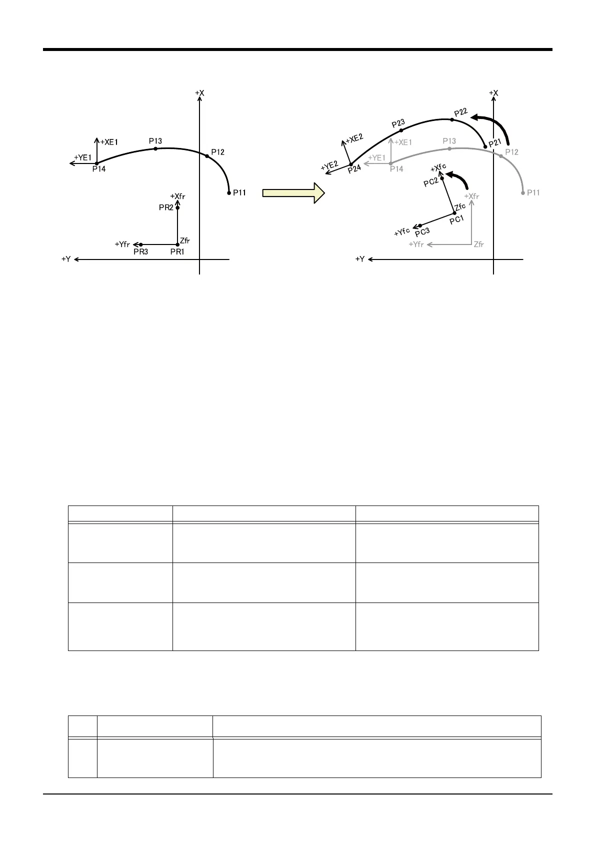
Fig.7-23:Frame transformation (Ex-T spline interpolation)
■Set data
Define the coordinate system by setting the following three position data items in the same manner as the
Fram function.
Origin position........................... Equivalent to PR1, PC1 in Fig. 7-22 and Fig. 7-23.
Position on X axis ..................... Equivalent to PR2, PC2 in Fig. 7-22 and Fig. 7-23.
XY plan +Y direction position.... Equivalent to PR3, PC3 in Fig. 7-22 and Fig. 7-23.
The X-, Y- and Z-axis coordinate values for a total of six position data items are set for the pre-transforma-
tion and transformed.
If the three position data items contain the same point or if the three position data items are on the same
line, the coordinate system cannot be defined and error L2041 (can’t calculate frame transformation coordi-
nates) will occur.
■Execution method
There are three methods of executing frame transformation.
Table 7-9:Frame transformation execution method
7.3.4 Work procedures
The work procedures for executing spline interpolation are listed below.
Table 7-10:Work procedures
Execution method Explanation Usage case
Execute with RT ToolBox2 Frame transformation is executed with the RT
ToolBox2 Spline File Edit screen. A spline file is
created using the transformation results as the
path points.
• When individually compensating the trans-
formed path point data using jog operation, etc.
• When using the transformed path point data as
the source data for another path.
Save coordinate system in
spline file
The coordinate system settings are saved in a
spline file, and the path points are sequentially
frame transformed when spline interpolation is
executed.
• To keep the coordinate values on the drawing as
the coordinate values for path points
• When coordinate system is fixed to one
Set coordinate system with
robot program
The coordinate system is set in the robot program
using the SetCalFrm command. The path points
are sequentially frame transformed using set
coordinate system when spline interpolation is
executed.
• To use multiple coordinate systems for one path
• To use sensors and compensate the path devia-
tion each time
No.
Step Work details
1 Creating the spline file
(Chapter "7.3.5")
The spline file is created using the RT ToolBox2 Spline File Edit screen, DXF File Import
function, or SplWrt command.
(1) Register the path points using the position teaching or import function.
(2) Set the signal output and numerical settings as necessary.
 Loading...