MTS 793 Controller Hardware
FlexTest IIm Controller Connections
182
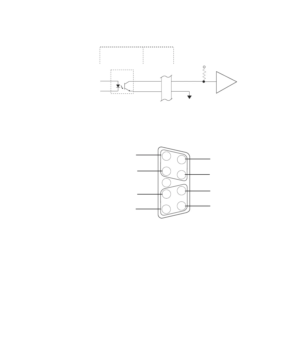
Connector pinouts The pin connections for the digital inputs and digital outputs are the
same. Each “D” style connector supports two channels.
J3 - 4
9
4
Ext Voltage
+CH4
-CH4
common
External Device
Opto-
Coupler
Digital I/O
Access Panel
498 Digital I/O
Transition Module
This figure shows how to
connect to an external
circuit using an external
power supply.
4
5
8
9
2
1
2
6
7
1
3
+12 V DC
+12 V DC
12 volt common
12 volt common
–Odd Channel #
–Even Channel #
+ Odd Channel #
+ Even Channel #
For example, the pins
associated with channels 1
and 2 are outlined.
The 12 volt supply is
reserved for the digital
inputs and should not be
used to power external
devices (it is rated for
maximum 250 mA current).
Artisan Technology Group - Quality Instrumentation ... Guaranteed | (888) 88-SOURCE | www.artisantg.com
 Loading...